
Active Area vs Viewing Area vs Module Outline in TFT Drawings
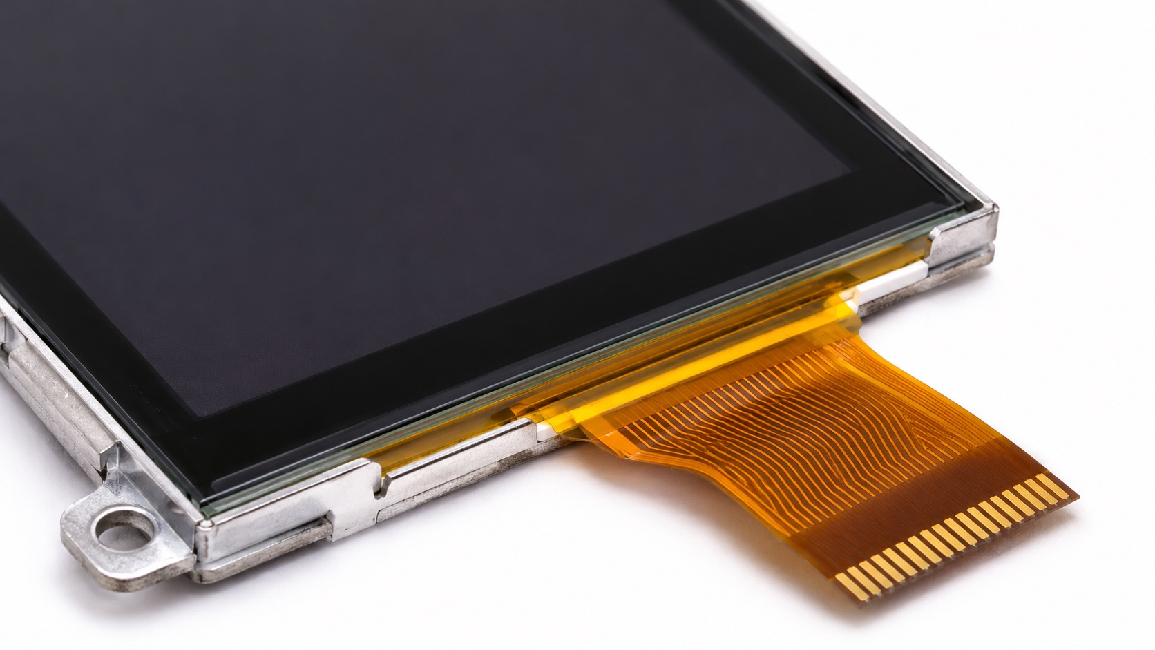
Active area is the image-producing region, viewing area is the designated visible window, and module outline is the assembly’s external envelope. These dimensions serve different purposes. Use the supplier’s drawing definitions because abbreviations and boundaries can vary.
Three Boundaries to Keep Separate
| Term | Common meaning | Main design use |
|---|---|---|
| AA, active area | Addressable image region | UI placement and visible pixels |
| VA, viewing area | Specified visible opening or window | Bezel and mask review |
| Outline | External module boundary | Enclosure fit and handling |
| Touch active area | Region qualified for touch input | Control placement and edge coverage |
A diagonal size does not define any of these complete rectangles. Nor does it identify their offset relative to a mounting datum. Two modules with the same resolution and nominal size can have different outlines, borders, and cable exits.
The Newhaven 4.3-inch module specification provides an example of a mechanical drawing with LCD and touch-area details. Treat it as an example of drawing organization, not a source of dimensions for a different module.
Why Centering by Outline Can Fail
An active area need not be centered within the mechanical envelope. Drivers, seals, cable attachments, and backlight construction can create asymmetric borders. If the enclosure centers the outside frame while the UI is expected to be visually centered, the result may look misaligned.
Locate the AA from approved datums. Check both axes and confirm whether dimensions refer to nominal edges, centerlines, or another feature. The mechanical drawing review workflow explains how to connect these dimensions to assembly constraints.
Bezel Openings Need a Tolerance Budget
Making a bezel opening exactly equal to nominal AA can hide edge pixels when parts shift. Making it too large can expose non-image borders, seals, or backlight structures. The right opening depends on the dimensional chain, viewing angle, front-stack spacing, and appearance requirements.
Consider an illustrative one-axis budget: an opening has 0.8 mm nominal clearance per side around the desired image region. If independent worst-case relative shifts consume 0.3 mm, 0.2 mm, and 0.1 mm in the same direction, only 0.2 mm remains on the limiting side. These invented numbers demonstrate arithmetic, not recommended clearances.
Include tolerances from module positioning, enclosure opening, cover printing, and adhesive placement where relevant. Check the opposite side and the other axis separately. Use worst-case or statistical methods deliberately; do not combine incompatible assumptions.
Viewing Angle Changes the Apparent Opening
A cover mask located above the pixel plane can obscure image edges at an oblique view. This parallax effect depends on layer separation and geometry. A centered front view may therefore pass while a user looking from the side sees clipped content.
Inspect a physical stack at the intended viewing positions. Include the cover glass and bonding configuration, gasket, bezel, and production mounting. Keep essential UI controls away from uncertain edges until the mechanical definition is settled.
Touch Area Is a Separate Requirement
The LCD image area and qualified touch region are not automatically identical. Edge sensitivity, cover decoration, sensor borders, and firmware configuration can affect usable input.
Overlay the touch drawing and display drawing in the same coordinate system. Check whether small buttons near corners remain accessible with the actual glove and enclosure. The glove operation guide offers a practical validation matrix.
Do not enlarge the UI beyond the qualified touch boundary simply because pixels remain visible there. Conversely, input outside the image may need suppression to avoid unintended actions.
Include Thickness and Cable Sweeps
A two-dimensional outline is not the full installation envelope. Connector height, component protrusions, FPC stiffeners, bend paths, and assembly movement require space. A cable may fit in its final position but be impossible to insert safely.
Request cross-sections and three-dimensional data when needed. Confirm maximum thickness and prohibited pressure areas. Support the module according to its mechanical guidance rather than using the glass as a clamping surface.
What to Approve
Freeze a drawing that identifies AA, VA, outline, touch region, datums, tolerances, thickness, and cable orientation. Keep a marked-up enclosure overlay as review evidence. On samples, verify edge visibility, mounting clearance, cable routing, and full-area touch.
The most useful acceptance record connects a visible symptom to a drawing requirement: clipped pixels, an exposed border, a shifted mask, or an inaccessible corner. That makes corrections reproducible instead of relying on a general judgment that the screen “looks off.”
Hero image: AI-generated editorial illustration.
Frequently Asked Questions
Are active area and viewing area identical?
Not necessarily. Confirm their boundaries and definitions on the supplier drawing.
Can the bezel opening equal the active area?
Evaluate tolerances and viewing geometry first; a nominal match can clip pixels in the assembled product.
Does the same diagonal mean the same outline?
No. Borders, offsets, frame size, thickness, and cable exits can differ.