Backlight Design & Driver Circuits for TFT LCD Displays
A TFT LCD relies on a backlight to illuminate its pixels, enabling the display to produce a visible image. Without a backlight, the LCD layer would simply modulate light from an external source and appear dark in most applications. If you’re not yet familiar with how TFT displays are structured, it’s worth reviewing What is TFT LCD for an introduction to panel layers and light modulation.
How TFT LCD Backlights Work
Most modern TFT LCDs use LED-based backlight systems. The LEDs can be placed along the panel edges (edge-lit) or behind the LCD (direct-lit). Their light passes through:
- Light Guide Plate (LGP) – Distributes light evenly.
- Diffuser Films – Smooth out brightness variations.
- LCD Pixel Layer – Controls light transmission to form images.
The backlight’s optical design impacts brightness, color consistency, and viewing quality. Choosing the correct panel type is also essential — as explained in TN vs IPS vs VA, different LCD technologies react differently to backlight uniformity and color stability.
Backlight Driver Circuit Basics
A backlight driver regulates LED current to ensure stable brightness and long life. Common designs include:
- Boost Converters – Step up voltage to drive multiple LEDs in series.
- Buck Converters – Step down voltage for lower-voltage LED arrays.
- Buck-Boost Designs – Handle wide input voltage ranges, ideal for automotive or industrial environments.
The choice of driver affects efficiency, dimming capability, and EMI performance — all critical in embedded systems.
Brightness Control Methods
Two main techniques are used:
- Analog Dimming – Adjusts the LED current directly. Simple but may shift LED color temperature.
- PWM Dimming – Switches LEDs on and off rapidly at a fixed current, varying the duty cycle to control brightness while maintaining color stability.
In high-resolution panels, understanding Resolution & Aspect Ratio is important, because screen size and pixel density determine how much backlight power is needed to maintain target brightness.
Thermal Management
LEDs generate heat, especially in high-brightness outdoor displays. Overheating reduces LED lifespan and causes brightness drop. Effective thermal design includes:
- Aluminum PCB substrates.
- Heat spreaders or metal housings.
- Adequate airflow and ventilation.
Industrial-grade IPS or VA panels — noted in TN vs IPS vs VA — often require more robust thermal solutions due to their higher brightness and wider viewing angles.
Power Efficiency Considerations
Backlight efficiency depends on:
- LED luminous efficacy (lumens per watt).
- Driver conversion efficiency.
- Optical film losses in the panel stack.
Reducing power consumption is critical for battery-powered devices, and optimizing LED placement relative to the display size (see Resolution & Aspect Ratio) can help balance brightness with energy savings.
Driver Selection Checklist
When a TFT module is evaluated for a real product, the backlight driver should be selected together with the panel, not after the mechanical design is already fixed. The LED string voltage, maximum current, dimming method, input supply range, and expected ambient temperature all influence the driver choice.
For small consumer products, the main concern is usually efficiency at moderate brightness. A handheld device may run the backlight at 20-60% duty cycle most of the time, so the driver should remain stable and efficient at light load. For an outdoor HMI or inspection terminal, the priority changes: the circuit must tolerate high LED current, enclosure heat, and long operating hours without thermal shutdown.
Useful questions during selection include:
| Question | Why It Matters |
|---|---|
| What is the LED string voltage at cold start? | The boost converter must have enough voltage headroom. |
| What is the maximum safe LED current? | Overdriving improves brightness briefly but shortens lifetime. |
| Is PWM dimming required? | Many UI systems need smooth low-brightness control. |
| Does the product need analog dimming? | Analog control can reduce flicker but may shift color. |
| What EMI limits apply? | Switching frequency, layout, and filtering affect certification. |
The driver data sheet should be checked against the LCD module drawing and the product power tree. A common mistake is choosing a driver that works on the bench at room temperature but has little margin when the input supply drops, the enclosure heats up, or the display is driven near full brightness.
Layout and EMI Notes
Backlight circuits are switching power circuits, so PCB layout has a direct effect on reliability and EMI. Keep the switching loop compact, place the input and output capacitors close to the driver IC, and avoid routing sensitive touch or display interface traces near the inductor. If the LCD FPC carries both backlight power and high-speed image data, ground assignment and return paths become even more important.
PWM frequency also deserves attention. A very low PWM frequency can create visible flicker or camera banding, while a poorly chosen high frequency may increase switching loss or make EMI peaks harder to control. Many products settle on a frequency high enough to avoid visible flicker, then verify the result with both human observation and pre-compliance measurements.
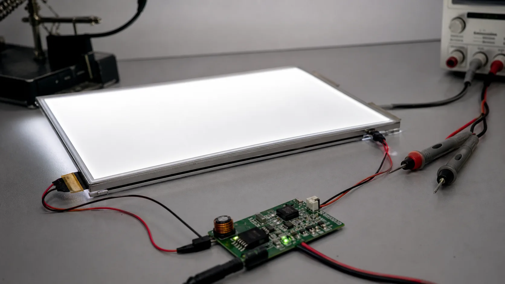
During prototype bring-up, engineers should measure:
- LED current at minimum, typical, and maximum brightness.
- Ripple on the backlight supply rail.
- Driver temperature after thermal soak.
- Startup behavior at low input voltage.
- EMI hot spots around the inductor, diode, and FPC connector.
These checks are inexpensive compared with redesigning the main PCB after certification testing.
Production Calibration
Even with the same driver and LCD model, actual brightness can vary between module batches because LEDs, light guide plates, and optical films have normal manufacturing tolerances. For products where display consistency matters, the system should support a calibration value stored in software, EEPROM, or factory configuration.
A simple production flow is often enough: measure luminance at a defined white screen, compare it with the product target, and adjust the PWM table or current setting. This prevents one unit from looking dim beside another and gives the product team a controlled way to balance readability, power consumption, and thermal stress.
For products that must look consistent over years of service, brightness calibration should be considered together with brightness calibration methods and color temperature targets. The backlight is not only a power load; it is part of the optical system users judge every time they turn the device on.
Reliability and Lifetime
Backlight lifetime is often expressed as L70, the point at which brightness drops to 70% of its original value. For industrial applications, L70 ratings above 50,000 hours are common.
To extend lifetime:
- Use high-quality LEDs.
- Avoid frequent high-current surges.
- Maintain junction temperatures within specification.
Conclusion
A well-designed backlight system is the backbone of any TFT LCD display, directly influencing image quality, power consumption, and product longevity. By combining an appropriate driver circuit, effective thermal management, and proper optical design, you can ensure consistent performance over the display’s entire service life.
👉 For more resources on industrial displays and updates, visit Industrial TFT Display Profile.
Frequently Asked Questions
Why does TFT LCD backlight design affect product reliability?
The backlight is one of the main power and heat sources in a TFT LCD system. Poor current control or thermal design can reduce LED lifetime, cause brightness drift, and create field reliability issues.
Is PWM dimming or analog dimming better for TFT backlights?
PWM dimming is common because it keeps LED color more stable across brightness levels. Analog dimming can reduce flicker in some designs, but it may shift color temperature and needs careful validation.
What should be checked during backlight prototype testing?
Check LED current, driver temperature, brightness at different duty cycles, startup behavior, ripple, visible flicker, and EMI around the inductor and FPC connector.