
How to Calculate TFT LCD Pixel Clock and RGB Timing
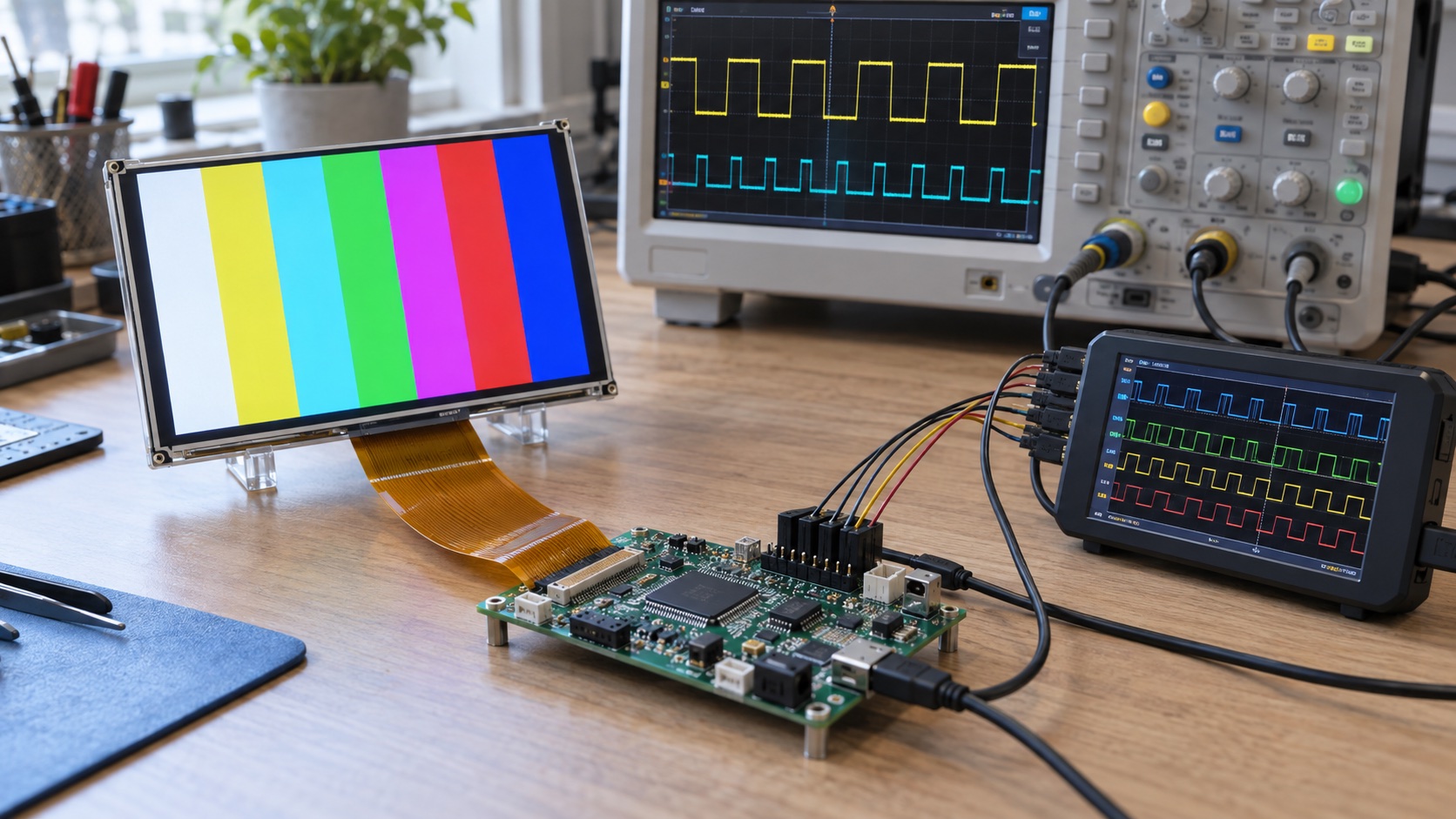
For a parallel RGB TFT, pixel clock equals horizontal total × vertical total × refresh rate. The totals include active image data and blanking intervals. Calculating only width × height × refresh rate underestimates the required clock whenever the panel needs porches or synchronization periods.
This guide shows the calculation, its mapping to controller settings, and the separate memory-bandwidth check. Numerical values below are an illustrative timing set, not a specification for all 800 × 480 displays. The hero is an AI-generated laboratory illustration.
The Pixel-Clock Formula
Htotal = Hactive + Hsync + Hback_porch + Hfront_porch
Vtotal = Vactive + Vsync + Vback_porch + Vfront_porch
Pixel_clock_Hz = Htotal × Vtotal × Refresh_Hz
Horizontal values count pixel-clock periods. Vertical values count complete lines. The refresh rate is the number of frames scanned per second, which can differ from the rate at which software renders new content.
The STMicroelectronics AN4861 application note documents this total-width and total-height approach for LTDC configuration. The arithmetic applies broadly to raster timing; register encodings remain controller-specific.
For the signal roles and wiring context, first review when to use an RGB interface TFT.
Worked Example: An 800 × 480 Display at 60 Hz
Assume the panel’s approved timing set is as follows:
| Parameter | Horizontal, pixel clocks | Vertical, lines |
|---|---|---|
| Active image | 800 | 480 |
| Sync width | 128 | 2 |
| Back porch | 88 | 25 |
| Front porch | 40 | 18 |
| Total | 1056 | 525 |
Then:
Htotal = 800 + 128 + 88 + 40 = 1056
Vtotal = 480 + 2 + 25 + 18 = 525
Pixel clock = 1056 × 525 × 60
            = 33,264,000 Hz = 33.264 MHz
The active-pixel-only estimate is 800 × 480 × 60 = 23.04 million pixels/s. It is not the required scan clock for this example, because it omits 170,400 blanking clock periods per frame.
The same numbers give useful measurement targets:
| Quantity | Calculation | Result |
|---|---|---|
| Pixel period | 1 / 33.264 MHz | About 30.06 ns |
| Line rate | 33.264 MHz / 1056 | 31.5 kHz |
| Line period | 1 / 31.5 kHz | About 31.75 µs |
| Frame period | 1 / 60 Hz | About 16.67 ms |
| Active line duration | 800 / 33.264 MHz | About 24.05 µs |
These values make a scope capture easier to interpret. If DE is active for the wrong number of clocks, changing the framebuffer will not repair the timing geometry.
Read the Datasheet’s Definitions Before Adding Numbers
Not every timing table uses the same notation. A symbol described as a back porch may include the sync pulse, while another document lists them separately. Some tables specify total blanking rather than individual front and back porches.
Check the waveform drawing as well as the table. Identify which edge begins a line, where active data starts, and which intervals overlap. Adding a combined interval to a separately listed sync width can double-count clocks.
The Newhaven 4.3-inch TFT specification is an example of a module document containing signal timing definitions and electrical constraints together. Its actual timing values differ from this article’s 800 × 480 example.
Archive the approved timing table with the project, as discussed in how to read a TFT datasheet. Record whether the design uses minimum, typical, or supplier-approved alternate values.
Convert Timing Counts Into Controller Registers
A controller may ask for interval lengths, accumulated positions, or counts encoded as value minus one. These are different representations of the same waveform.
For a controller using an accumulated, minus-one convention, the illustrative horizontal values might become:
Sync end         = Hsync - 1                    = 127
Back-porch end   = Hsync + Hback_porch - 1      = 215
Active-area end  = Hsync + Hback_porch + 800 - 1 = 1015
Total-line end   = Htotal - 1                   = 1055
This is an encoding example, not a universal register recipe. Some software APIs accept raw lengths and perform the subtraction internally. Applying minus one twice shifts every boundary.
Check horizontal and vertical units separately. RGB timing measured in pixel clocks must not be pasted into MIPI DSI registers that expect lane-byte-clock cycles. The MIPI lane-rate calculation guide explains that separate clock domain.
Match Clock Edge, Polarity, and DE Mode
A correct clock frequency can still produce an incorrect image. Confirm:
- Which pixel-clock edge the panel samples.
- Data setup and hold requirements at the module connector.
- Active levels for HSYNC, VSYNC, and DE.
- Whether the panel uses DE mode, sync mode, or a documented combination.
- RGB data mapping and the configured bus width.
Read polarity descriptions carefully: an API’s “inverted clock” setting may describe the output transition rather than the panel’s sampling edge. Verify the resulting waveform instead of relying on the option name.
In a 24-bit parallel RGB888 interface, one complete pixel is typically transferred per pixel clock. Multiplying the scan clock by 24 would confuse the parallel bus with a serialized link.
Check the Clock the PLL Can Actually Generate
Suppose the target is 33.264 MHz, but the selected PLL configuration generates 33.000 MHz. With the same totals:
Actual refresh = 33,000,000 / (1056 × 525)
               ≈ 59.52 Hz
Whether that is acceptable depends on the panel’s clock and frame-rate limits, not on whether the difference seems small. Include oscillator tolerance and any relevant clock variation in the comparison.
If adjusting porch counts is permitted, recalculate all boundaries and verify minimum intervals. Do not shorten blanking below the specification simply to obtain an exact 60.000 Hz figure.
Calculate Framebuffer Capacity and Bandwidth Separately
For the example’s active area:
| Stored format | Bytes per pixel | One framebuffer | Active scanout at 60 Hz |
|---|---|---|---|
| RGB565 | 2 | 768,000 bytes | 46.08 MB/s |
| Packed RGB888 | 3 | 1,152,000 bytes | 69.12 MB/s |
| ARGB8888 | 4 | 1,536,000 bytes | 92.16 MB/s |
These are decimal byte counts and a one-read-per-active-pixel baseline. Actual memory traffic can be higher because of stride padding, bus transactions, blending layers, rendering, cache activity, and other masters. Verify which stored formats the controller supports; not every pipeline offers a packed three-byte framebuffer.
Double buffering doubles framebuffer storage, but does not automatically double scanout reads. Rendering the next buffer adds its own traffic. A controller FIFO can still underrun if memory service arrives too late, even when average bandwidth appears sufficient.
Bench Validation and Troubleshooting
Start with fixed color bars or a border pattern and disable unrelated rendering work. Measure PCLK, line period, frame period, and DE width. Then add normal CPU, graphics, and communication loads while monitoring underrun flags.
| Symptom | First timing or data check |
|---|---|
| Image shifted left or right | Horizontal active-start position and DE alignment |
| Image shifted vertically | Vertical start and line totals |
| Repeating or wrapped image | Active width, stride, and framebuffer address |
| Noise that grows with CPU load | Memory latency and FIFO underrun |
| Stable geometry but wrong colors | RGB mapping, pixel format, and bit order |
| Horizontal tear during animation | Buffer ownership and frame synchronization |
Use the lines and artifacts guide for physical interface faults and the screen-tearing guide for buffer-update problems.
Keep the approved timing set, calculated clock, achievable PLL output, measured waveforms, and stress-test results together. That record turns a working demonstration into a repeatable display configuration.
Frequently Asked Questions
How do I calculate an RGB TFT LCD pixel clock?
Multiply total horizontal pixels by total vertical lines and frame refresh rate. Horizontal total includes active width, horizontal sync, back porch, and front porch. Vertical total includes active height, vertical sync, back porch, and front porch.
What pixel clock does an 800 x 480 LCD need?
Resolution alone is insufficient. In an illustrative timing set with 1056 total pixels per line, 525 total lines, and 60 Hz refresh, the pixel clock is 33.264 MHz. Use the actual panel's specified totals and allowed clock range.
Do I multiply RGB pixel clock by 24 for RGB888?
Not for a parallel 24-bit RGB interface carrying one full pixel each clock. The bus transfers the color bits in parallel. Serial-link bit rate and framebuffer bandwidth require separate calculations.
What are front porch and back porch?
They are blanking intervals around synchronization and active image data. Horizontal porches are normally specified in pixel-clock periods, while vertical porches are normally specified in lines. Some datasheets combine sync and porch intervals, so check the definitions.
Can I lower pixel clock to reduce refresh rate?
Only within the panel and host's supported timing limits. With totals unchanged, refresh rate changes in proportion to pixel clock. Verify minimum refresh, image quality, clock tolerance, and memory behavior before using the new mode.