
Ghost Touches on Capacitive Screens: Causes and Fixes
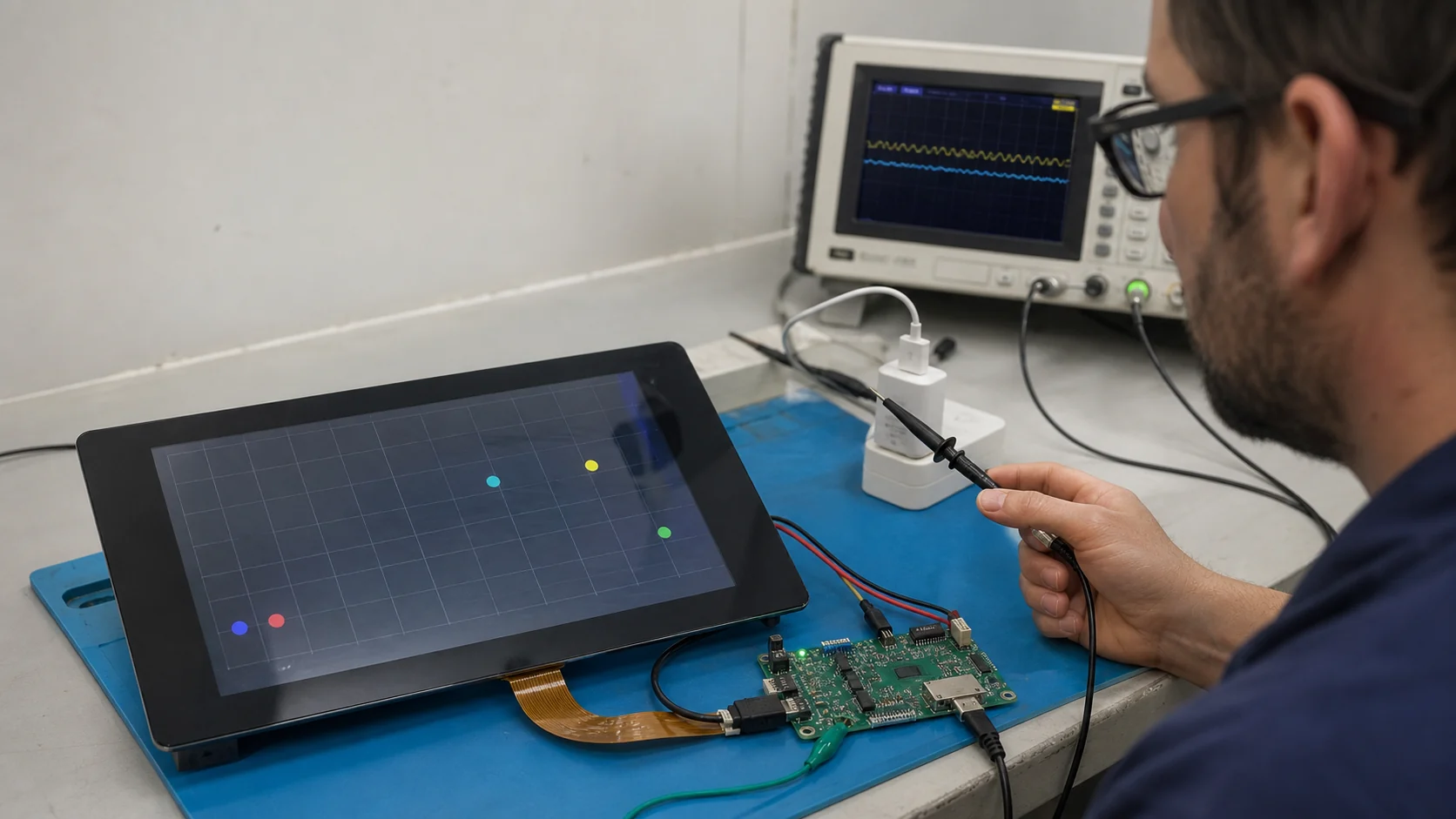
Ghost touches are false touch coordinates reported when the user did not intentionally touch the screen. The most common causes are electrical noise, poor grounding, charger coupling, water, display/backlight interference, damaged or poorly routed FPCs, and touch-controller tuning that cannot separate a real finger signal from noise and baseline drift.
The correct fix is not simply “increase sensitivity” or “raise the threshold.” First capture raw touch data and correlate the false event with power source, display activity, backlight PWM, radio, water, temperature, and enclosure state. Then correct the physical cause and retune the final assembled product.
Define the Symptom Precisely
Record what “ghost touch” means in the failing product:
- A single random coordinate.
- A continuous moving contact.
- Multiple simultaneous points.
- A touch that remains after the finger lifts.
- An edge-only or corner-only false contact.
- False touches only during charging or radio activity.
- False touches after water, condensation, cleaning, or ESD.
- Correct controller data but incorrect UI behavior.
If the panel reports no touch at all, use why a TFT touchscreen is not responding. Ghost touch and no-response faults can share power, reset, FPC, and firmware causes, but their tuning evidence differs.
Ghost-Touch Cause Matrix
| Trigger pattern | Likely cause | First controlled test |
|---|---|---|
| Only while connected to one charger | Common-mode/conducted noise | Battery vs approved supplies; raw-data capture |
| Starts when backlight brightness changes | PWM/boost coupling or ground impedance | Fixed backlight level; scope PWM and touch raw counts |
| Starts with display animation | LCD/DSI/RGB noise coupling | Static image vs high-activity pattern |
| Appears with droplets or wet film | Liquid coupling and baseline behavior | Defined droplet/wet-finger test |
| Edge/corner false points | Sensor/cover stack, grounding, tuning | Raw heat map and cover-lens inspection |
| Appears after enclosure assembly | Metal, air gap, pressure, adhesive, ground change | Bare stack vs final enclosure |
| Appears after ESD and persists | Controller upset or damaged path | Reset recovery and ESD event log |
| UI reacts but controller log is clean | Driver/application software | Compare raw, report, input event, and UI logs |
Step 1: Capture Raw Data, Not Only Coordinates
Use the touch-controller tuning tool or diagnostic registers to log:
- Raw/self or mutual-capacitance values.
- Baseline/reference values.
- Signal delta for a real finger.
- Peak-to-peak noise with no touch.
- Per-channel thresholds.
- Reported coordinates and touch count.
- Controller status, reset, and fault flags.
Record at least four conditions: no touch, normal finger, known failure trigger, and recovery. A coordinate log alone cannot show whether the problem is electrode noise, baseline tracking, the controller’s classification, or host software.
Signal-to-noise ratio is a core metric. Measure it using the controller vendor’s defined method and tune with margin across production, temperature, humidity, and cover-lens tolerance.
Step 2: Reproduce with a Controlled Matrix
Change one condition at a time:
- Battery versus external power.
- Approved supply versus failing charger.
- Backlight off, fixed low, fixed high, and PWM dimming.
- Static black/white/checkerboard/animated display patterns.
- Radios off versus transmitting.
- Bare module versus final enclosure.
- Dry finger, glove, wet finger, droplets, and continuous water film.
- Room, cold, and hot conditions.
Log raw touch data with each state. The goal is correlation, not a one-time pass.
Step 3: Check Power and Ground Noise
Measure touch-controller supply and ground at the controller during false events. Look for ripple, transients, common impedance, reset glitches, and ground movement caused by backlight, processor, radio, or external supply currents.
Useful comparisons include:
- Battery operation with no earth-referenced cable.
- Isolated lab supply.
- Production charger/cable combinations.
- USB connected to a grounded computer.
- Device held in hand versus resting on an insulating surface.
A supply can maintain the correct DC voltage while carrying enough common-mode or high-frequency noise to disrupt capacitive sensing. Use appropriate probes and avoid long ground leads.
Step 4: Investigate Charger-Dependent Ghost Touch
If the issue appears only while charging:
- Test multiple compliant chargers and cables.
- Compare two-prong and earth-referenced setups where applicable.
- Measure controller raw noise with and without a finger.
- Inspect isolation, common-mode emissions, Y-capacitor strategy, and ground coupling at the system level.
- Confirm shield/ground recommendations for the touch controller.
Do not approve the design based only on a quiet laboratory supply. Validate the actual charger family and realistic user grounding conditions.
Step 5: Correlate Display and Backlight Activity
The LCD interface, display driver, backlight boost converter, and PWM edges can couple into touch electrodes or their ground reference.
Run these tests:
- Static frame versus maximum animation bandwidth.
- Backlight disabled versus enabled.
- Analog/fixed current versus PWM dimming.
- Several PWM frequencies and duty cycles within driver limits.
- Display sleep/wake and brightness transitions.
If raw counts show periodic noise locked to PWM or frame timing, improve routing, grounding, shielding, frequency planning, edge control, and scan synchronization before raising thresholds.
The site’s EMI testing guide provides a broader method for correlating noise sources and immunity failures.
Step 6: Inspect Sensor, FPC, and PCB Layout
Review the complete touch signal path:
- Sensor electrode geometry and parasitic capacitance.
- Trace length, width, spacing, and ground/shield strategy.
- Distance from clocks, switching nodes, antennas, motors, and LEDs.
- FPC routing over display and backlight circuitry.
- Connector ground/reference pins.
- Series resistance and controller-support components.
- ESD device capacitance and placement.
- Air gaps, adhesive voids, and metal near the sensor.
Damage or contamination at the FPC can affect only certain channels, creating repeatable edge or corner ghosts. Compare per-channel raw data and continuity with a known-good assembly.
Step 7: Validate the Final Cover Stack
Touch performance depends on cover material, thickness, dielectric constant, adhesive, printing, air gaps, and mechanical support. Tune the controller with the final stack, not with a bare sensor.
Inspect for:
- Cover lens thicker than the tuning sample.
- Adhesive voids or variable bond thickness.
- Conductive decorative coating or nearby metal frame.
- Black-mask/ink steps that change stack thickness.
- Enclosure pressure or bending.
- Grounded metal moved closer during assembly.
The capacitive touch panel basics and HMI cover-lens design guide explain the sensor and front-surface interaction.
Step 8: Test Water and Condensation Correctly
Water is not one condition. Test:
- Single droplets at center and edge.
- Several separated droplets.
- Continuous film.
- Wet finger.
- Flowing water if relevant.
- Water bridging the active area to grounded bezel/metal.
- Condensation after temperature transition.
Define expected behavior. The system may continue tracking a finger, suppress all touch until water clears, or allow limited functions. “No ghost touch” alone is incomplete unless required real touches are also tested.
Use controller-supported shield, guard, water-rejection, and baseline strategies when available. Do not assume a software filter can compensate for an unsuitable sensor/enclosure geometry.
Step 9: Review Thresholds, Baseline, and Filters
Tune from measurements:
- Finger/touch threshold.
- Noise and negative-noise thresholds.
- Hysteresis.
- Debounce and persistence.
- Baseline update rate.
- Low-baseline reset behavior.
- Scan frequency and multi-frequency operation.
- Spatial filters and touch-size rejection.
A threshold too low reports noise as touch. A threshold too high misses light touches, gloves, thick glass, and edges. Baseline tracking that is too fast can absorb a real touch; too slow can retain environmental drift.
Validate the chosen settings across several assemblies and environmental corners, not only the quietest sample.
Step 10: Separate Controller Output from Host Software
Trace one event through the stack:
raw electrode data → controller classification → coordinate report → I2C/SPI driver → OS/input event → coordinate transform → UI action
Check:
- Interrupt storms and missed clear/acknowledge operations.
- Partial or corrupted I2C reads.
- Touch-count and packet-length parsing.
- Stale coordinates reused after touch-up.
- Rotation, scaling, and axis transforms.
- Multi-touch slot lifecycle.
- Event queue overflow or duplicate dispatch.
- Controller reset without driver reinitialization.
If controller coordinates are clean but the application sees ghosts, do not retune the sensor. Fix the software boundary where the false event first appears.
Step 11: Check ESD and Recovery
An ESD event can reset the touch controller, corrupt communication, latch an interrupt, or damage a channel. Log resets and communication errors, then verify automatic recovery:
- Detect timeout, invalid packet, or reset status.
- Reset the controller when required.
- Reapply the approved configuration/tuning.
- Clear stale touches and input slots.
- Confirm normal reporting without rebooting the product.
Product-level ESD design includes the discharge path through cover, bezel, chassis, ground, connector, and PCB. Protection placed at the controller but far from the entry point may be insufficient.
Step 12: Confirm the Fix with Production-Representative Samples
Test multiple touch assemblies, controllers, cover stacks, chargers, and temperature/humidity conditions. Include tolerance extremes, not only engineering samples.
Track:
- Real-touch signal.
- No-touch noise.
- Worst-case SNR.
- False-touch count over time.
- Missed-touch count.
- Coordinate accuracy and edge performance.
- Recovery after water, ESD, sleep, and power transitions.
The final acceptance test should detect both excessive sensitivity and insufficient sensitivity.
Common Ghost-Touch Mistakes
- Raising thresholds before measuring raw noise.
- Tuning a bare sensor instead of the final cover stack.
- Testing only on battery or a laboratory supply.
- Calling every UI event a touch-controller problem.
- Ignoring display and backlight timing correlation.
- Applying filters that add unacceptable latency.
- Treating all water conditions as equivalent.
- Rebooting after ESD instead of testing automatic recovery.
Prevention Checklist
- Select a controller with raw-data tools and appropriate noise/water features.
- Route touch signals away from switch nodes, clocks, and antennas.
- Plan grounding, shielding, charger, and enclosure together.
- Freeze cover glass, adhesive, ink, and metal geometry before final tuning.
- Keep raw-data logging and a touch heat map in diagnostic firmware.
- Validate approved chargers and cables with users holding the product.
- Test wet, glove, temperature, ESD, sleep/wake, and aging conditions.
- Control touch-controller IC, firmware, configuration, and PCN changes.
Engineering References
- Infineon AN85951: PSOC 4 and PSOC 6 MCU CAPSENSE design guide — signal-to-noise, tuning, layout, overlay, liquid tolerance, and noise mechanisms.
- Microchip: Guide to Design Touch Sensor — sensor construction, layout, noise, grounding, and touch-design workflow.
The references describe controller-family design methods. Apply the documentation and tuning tools for the exact PCAP controller and sensor stack used in the product.
Frequently Asked Questions
What causes ghost touches on a capacitive touchscreen?
Ghost touches are false coordinates reported without an intended finger contact. Common causes include conducted or radiated noise, poor grounding, noisy chargers, water, high parasitic capacitance, display/backlight coupling, incorrect touch tuning, baseline drift, ESD events, damaged FPCs, or firmware parsing errors.
Why does my touchscreen have ghost touches only while charging?
A charger can introduce common-mode and conducted noise between the device and earth. A finger changes that coupling and can inject noise into the sensor. Compare battery operation with several compliant power sources and measure touch raw data, power, and ground noise.
Can water cause capacitive ghost touches?
Yes. Water changes capacitance and can couple multiple electrodes, especially when it connects the active area to grounded metal or a user's hand. Water-tolerant designs use suitable sensor geometry, shielding or guard strategies, controller algorithms, thresholds, and explicit wet-condition validation.
Should I fix ghost touches by increasing the touch threshold?
Increasing threshold may suppress false reports but can reduce sensitivity, glove operation, and edge performance. First measure signal, noise, baseline behavior, and the noise source. Tune thresholds only after the hardware and environmental causes are understood.
How can I prove whether ghost touches come from hardware or software?
Log raw electrode data, controller-reported coordinates, interrupt timing, and application events together. If raw data or controller coordinates show the false touch, investigate sensing hardware and tuning. If raw/controller data are clean but the UI reacts, investigate driver parsing, coordinate transforms, event queues, and application logic.