
Choosing PWM Frequency for LCD Backlight Dimming
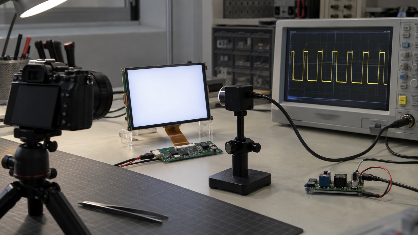
Choose LCD backlight PWM frequency from the LED driver’s limits and the product’s measured dimming behavior, not from a universal number. Higher frequency can reduce some visible or camera-related modulation, but it also shortens low-duty pulses and reduces available timer steps. The best setting satisfies the required brightness range, image-capture conditions, noise, and electrical performance together.
This guide concerns LED-backlit TFT modules. It separates the input control waveform from actual LED current and optical output. Calculations are illustrative engineering examples; the hero is an AI-generated laboratory illustration.
First Identify What the PWM Pin Actually Does
There are several architectures behind a pin labeled PWM or DIM:
| Architecture | What the input controls | What to measure |
|---|---|---|
| Direct current gating | LEDs switch between on and off current | Current pulse width and optical pulse shape |
| PWM-to-analog control | Duty cycle sets an average current reference | Settling, ripple, and low-current behavior |
| Internally regenerated PWM | Input duty is translated to another timing domain | Output frequency, resolution, and synchronization |
| Hybrid dimming | Analog current and PWM both change | Transition points and optical continuity |
For example, the TI TPS61169 datasheet specifies a 5–100 kHz input PWM range and describes duty-cycle control of the feedback reference rather than direct bursting of LED current. Its PWM pin frequency is therefore not a simple statement of the optical pulse frequency.
Read the specific driver’s dimming section before choosing a timer setting. The backlight driver-circuit guide provides context for constant-current regulation and LED-string topology.
Separate Three Frequencies
The system may contain a converter switching frequency, a brightness-control PWM frequency, and a display frame refresh rate. They serve different purposes and can differ by orders of magnitude.
- Converter switching transfers energy through inductors or capacitors.
- Dimming control determines average LED light output.
- Display refresh updates the liquid-crystal image.
Changing an RGB pixel clock does not directly set LED dimming frequency. Similarly, a 1 MHz boost converter does not establish that the backlight’s optical output is modulated at 1 MHz.
When debugging flicker, capture both the light output and the relevant electrical signal. A bright/dark image transition, a PWM pulse train, and a power-supply oscillation can look similar to a user but require different fixes.
Calculate Minimum On-Time at the Required Brightness
For direct PWM gating:
PWM period = 1 / PWM frequency
On-time = Duty_cycle / PWM frequency
Minimum usable duty ≈ Minimum useful on-time × PWM frequency
The last relationship is a first estimate. Current rise/fall behavior, optical response, and the driver’s internal control can impose further limits.
Assume an illustrative driver needs a useful LED on-time of at least 1 µs:
| PWM frequency | Period | Estimated minimum duty | Idealized dimming ratio |
|---|---|---|---|
| 1 kHz | 1000 µs | 0.1% | 1000:1 |
| 5 kHz | 200 µs | 0.5% | 200:1 |
| 20 kHz | 50 µs | 2% | 50:1 |
| 40 kHz | 25 µs | 4% | 25:1 |
These are mathematical results for the assumed 1 µs limit, not recommended operating points. A different driver may have a much shorter pulse, analog dimming, or a different method for producing low brightness.
Increasing frequency without checking this relationship can make the lowest brightness setting too bright, uneven, or non-monotonic.
Account for Timer Resolution
For a simple edge-aligned counter:
Counts per PWM period = Timer_clock / PWM_frequency
Approximate duty steps = Counts per period
With an illustrative 80 MHz timer and no additional prescaler, 20 kHz provides 4000 counts per period, or about 12 bits of nominal duty resolution. At 40 kHz, that becomes 2000 counts, about 11 bits.
The usable optical steps can be fewer because the driver cannot reproduce every short pulse. Center-aligned modes, timer encodings, and prescalers also change the calculation. Check the actual peripheral configuration rather than assuming its advertised counter width is the effective dimming resolution.
Use a brightness mapping curve appropriate to the product. Human brightness perception is not a linear meter, so equal duty increments need not appear equally spaced. Calibrate measured luminance and user-facing settings separately.
Dithering Can Change the Low-Brightness Waveform
Some drivers extend apparent dimming resolution by varying pulses over several periods. This can produce finer average light levels but also create lower-frequency components or pulse skipping at the bottom of the range.
The TI LP8864-Q1 datasheet describes output PWM dithering and behavior near its minimum LED pulse width. It demonstrates why a configured output frequency alone does not fully describe the low-brightness optical waveform.
Capture a long enough time window to see the entire repeating pattern. A scope view containing only two PWM periods can miss slower modulation introduced by the dimming algorithm.
Test Camera Banding Under Real Capture Conditions
Camera banding depends on the relationship between light modulation, exposure time, and sensor row timing. A setting that looks clean at one exposure can show bands at another, especially with a rolling shutter.
Test the actual camera types and expected conditions:
- Short and long exposures.
- Low, medium, and maximum brightness.
- Automatic and locked exposure where relevant.
- Different frame rates and moving camera views.
- Static images and normal display animation.
If the product must be filmed, evaluate measured optical modulation rather than assuming an above-audible PWM frequency guarantees clean video. A phone video is useful for reproducing a symptom, but it is not a calibrated measurement of flicker.
Check Acoustic Noise and EMI Together
PWM can modulate electrical loads and excite audible behavior in capacitors or magnetic components. Moving a control frequency upward may help one mechanism while leaving subharmonics, pulse skipping, or converter interactions.
Faster switching edges can also increase high-frequency emissions or couple noise into touch sensing. Keep control traces, current return paths, and backlight switching loops deliberate. Use the embedded-system EMI guide when the problem correlates with emissions or touch disturbance.
Do not judge a design by frequency alone. Test the assembled enclosure, because mounting and mechanical resonance can change the audible result.
A Practical Frequency-Selection Workflow
- Identify the exact driver and whether input PWM gates, converts, or regenerates current.
- Record allowed frequency, input levels, minimum pulse/duty, and startup behavior.
- Define the minimum luminance and usable brightness steps the product needs.
- Calculate pulse-width and timer-resolution limits for candidate settings.
- Measure current and optical output at several duty levels, especially near minimum.
- Test camera behavior, audible noise, touch operation, and EMI in the product assembly.
- Select the setting with adequate margin and retain the test conditions.
When the requirements conflict, consider a supported analog or hybrid dimming mode, a different driver, or a revised minimum-brightness requirement. Do not compensate by overdriving peak LED current outside the module rating.
What a Useful Validation Record Contains
Record the driver part number, hardware revision, timer configuration, input frequency, actual optical frequency, minimum on-time, peak LED current, luminance steps, and temperature. Include any dither or hybrid-mode settings.
Measure brightness using a repeatable geometry, as described in TFT brightness calibration. If illumination disappears rather than dims smoothly, continue with the no-backlight troubleshooting guide.
The result should be a documented operating range: brightness commands that produce stable light under the product’s actual viewing and capture conditions.
Frequently Asked Questions
What PWM frequency should I use for an LCD backlight?
Start with the LED driver's allowed input range and dimming architecture. Then select a frequency that meets minimum brightness, pulse-width, timer-resolution, optical, acoustic, and EMI requirements. There is no universal frequency for every TFT backlight.
Does a PWM input mean the LED current is pulsed at the same frequency?
No. A driver may directly gate LED current, regenerate PWM at another frequency, or convert the input duty cycle into an analog current reference. Measure LED current or optical output and read the driver's dimming description.
Why does a backlight stop dimming smoothly at low duty cycle?
The requested on-time may approach the driver's minimum useful pulse width or the timer's resolution. Settling, pulse skipping, quantization, and internal dimming algorithms can then dominate the light output.
Will a 20 kHz backlight PWM eliminate camera banding?
Not necessarily. Camera exposure, rolling-shutter timing, modulation depth, and the actual optical waveform determine banding. Test the intended cameras and exposure settings across the full brightness range.
Can I connect the backlight LEDs directly to a PWM GPIO?
A GPIO is a control signal, not generally an LED-string current source. Use the specified constant-current driver and apply PWM to its approved dimming or control input, with compatible logic levels.