
LCD Has an Image but No Backlight: What to Check
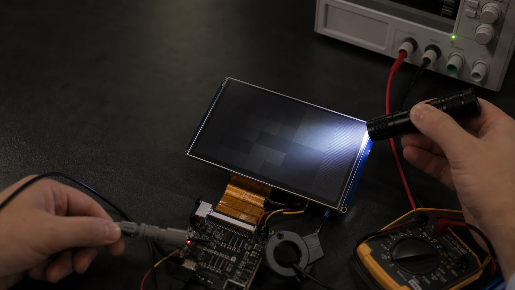
If an LCD shows a faint but correct image under a flashlight, the LCD pixel path is working and the problem is in the backlight subsystem. Check backlight enable and PWM first, then input power, regulated LED current, boost voltage, driver fault status, the LED string, and FPC continuity. Never test an unknown LED backlight with an unrestricted voltage source.
This symptom is easier to isolate than a completely blank display because the visible image proves that the host, image data, much of the timing, and the LCD cell are operating. The remaining task is to trace the energy path from the power source through the LED driver to the module’s backlight pins.
Confirm the Symptom with the Flashlight Test
Run a high-contrast test pattern or known menu. In a dim room, shine a flashlight across the front of the display at a shallow angle.
- Stable image visible: focus on the LED backlight and its control circuit.
- No image visible: the fault may include LCD power, reset, interface, or initialization; use the TFT white-screen troubleshooting guide or broader display checks.
- Image visible only intermittently: log both display and backlight signals because a shared power or reset event may affect both.
Do not confuse an extremely low dimming level with a failed backlight. Command maximum allowed brightness during diagnosis, while remaining within the LED current and thermal limits.
Understand the Backlight Power Path
A typical TFT backlight path is:
Input supply → LED driver/boost converter → current sink → LED string → return
Control inputs may include:
- Hardware enable (
EN,BL_EN, or similar). - PWM dimming input.
- Analog brightness/current-setting input.
- I2C/SPI configuration and fault registers.
- Thermal or ambient-light control from firmware.
Small modules may expose one anode and one cathode for a single string. Larger modules may contain multiple strings and require current matching. Some modules include the driver; many expose only the raw LED string and require an external constant-current driver.
The TFT backlight and driver-circuit guide explains these architectures in more detail.
Fast Symptom-to-Cause Table
| Backlight behavior | Likely cause | First measurement |
|---|---|---|
| Never flashes at startup | Enable/PWM, missing input, open path | EN, PWM and driver VIN |
| Flashes briefly then turns off | Open string, overvoltage, undervoltage, thermal/fault latch | Fault status and boost waveform |
| Very dim at maximum command | Low LED current, analog dimming, supply limit, aged LEDs | String current and input power |
| Works when FPC is moved | Connector or cracked FPC trace | Continuity and connector inspection |
| Works cold, fails hot | Thermal shutdown, marginal solder joint, LED degradation | Driver temperature and current vs time |
| One dark region on a large display | One open string or local optical fault | Individual channel current/fault flag |
| Brightness pulses or restarts | Input droop, unstable control loop, protection cycling | VIN, VBOOST, EN and PWM together |
Step 1: Verify Enable and PWM at the Driver Pin
Measure the actual LED-driver pins rather than assuming the MCU state is reaching them.
For enable, check:
- Required active level and threshold.
- Pull-up or pull-down population.
- Delay relative to the input supply and panel startup.
- Firmware GPIO mode after boot and sleep transitions.
- Any load switch or transistor that inverts the signal.
For PWM, check:
- Duty cycle at the moment the backlight should be on.
- Polarity expected by the driver.
- Logic-high/low levels at the driver voltage domain.
- Frequency within the device’s accepted range.
- Whether a missing PWM signal means full brightness or shutdown.
A meter may average PWM into a misleading voltage. Use an oscilloscope and capture startup, normal operation, dimming transitions, and failure.
Step 2: Check Input Power Under Load
Measure the LED driver’s input voltage at its pins while the backlight is commanded on. A boost driver can draw much more input current than the LED current because it converts a lower input voltage into a higher string voltage.
Estimate input power before blaming the display:
PLED ≈ VLED × ILED
IIN ≈ PLED / (VIN × efficiency)
For multiple strings, sum their output power. Add margin for startup, low input voltage, component tolerance, and thermal derating.
If input voltage dips when enable rises, inspect the regulator limit, battery impedance, cable resistance, ground return, bulk capacitance, and inductor saturation. A stable 5 V with the backlight off does not prove that the rail can supply the enabled load.
Step 3: Measure Boost Output Safely
Backlight voltage may be much higher than the logic rail. Use a probe and instrument rated for the expected voltage, keep the ground connection short, and avoid slipping across fine-pitch pins.
Interpret boost behavior:
- No rise above input: driver disabled, no switching, bad inductor/diode, missing input, or internal fault.
- Rises toward maximum then shuts down: open LED string or disconnected module is likely.
- Rises but current remains low: current-sense path, dimming command, current setting, or LED degradation may be limiting output.
- Cycles repeatedly: protection may be retrying after open, short, undervoltage, overtemperature, or overload.
Read driver status registers or fault pins before power cycling, because some faults latch until reset and contain the most useful evidence.
Step 4: Measure LED Current, Not Just Voltage
LED brightness is determined primarily by current. The string voltage is a consequence of the number of LEDs, their temperature, and their individual forward voltages.
Use one of these controlled methods:
- Measure the driver current-sense voltage and calculate current from the documented resistor relationship.
- Insert a suitable current meter only when the circuit and instrument burden voltage are understood.
- Use a current-limited LED tester rated for the expected string voltage.
- Test individual driver channels using built-in diagnostics when available.
Do not connect a bench supply directly across the string at an arbitrary voltage. Once LEDs conduct, a small voltage increase can cause a large current increase.
Step 5: Check the LED String and Module FPC
With power removed, inspect the backlight pins and cable. Common problems include:
- Reversed
LED+andLED−. - Wrong pin mapping between module revisions.
- Backlight pins omitted from a shared connector.
- Cracked trace at the FPC bend or stiffener.
- Incomplete connector insertion.
- Connector contact side mismatch.
- Solder damage after hot-air rework.
- LED string opened by ESD, flexing, or overcurrent.
Compare resistance/diode readings with a known-good module, but remember that multiple series LEDs may exceed a handheld meter’s test voltage. An “open” meter reading does not alone prove an open string.
Step 6: Interpret Driver Protection Correctly
Modern backlight drivers may detect:
- Open LED string.
- LED short or short to ground.
- Boost overvoltage.
- Input undervoltage.
- Overcurrent.
- Thermal warning or shutdown.
- Missing current sink headroom.
An open string often causes the boost converter to increase output voltage while trying to establish current. When it reaches its overvoltage or maximum limit, the driver disables the affected channel or the entire output. This is why a backlight may flash once and then remain dark.
Record the sequence of VIN, EN, PWM, switching node, boost output, and fault signal. The order of events distinguishes a cause from a protection response.
Step 7: Rule Out Firmware and System Policies
Backlight behavior is often controlled above the driver level. Check whether firmware intentionally turns it off because of:
- Ambient-light calculation.
- Inactivity timeout or sleep state.
- Thermal limit.
- Battery-saving mode.
- Boot failure or watchdog reset.
- Display-present detection.
- Brightness value stored as zero or corrupted configuration.
Temporarily command a fixed safe duty cycle in a minimal diagnostic build. Do not bypass hardware thermal or overcurrent protection.
Step 8: Test Temperature and Time Dependence
Run the backlight at controlled current while monitoring module temperature, driver temperature, input power, and brightness. Failure after several minutes can indicate:
- Driver thermal shutdown.
- Insufficient PCB copper or airflow.
- Inductor or diode overheating.
- Marginal connector resistance.
- LED string intermittency.
- Excess current or excessive ambient temperature.
Brightness naturally changes with LED temperature and age, but a complete shutdown requires electrical investigation. For measurement consistency, use the methods in brightness calibration for TFT LCDs.
Step 9: Isolate Board, Driver, and Module
Use known-good substitution:
- Test the suspect module with a controlled current source or supplier evaluation setup.
- Test a known-good module on the suspect board.
- If separate, test the driver stage with an appropriate dummy load or diagnostic method from its datasheet.
- Compare fault registers, string current, and boost voltage.
If a known-good module also fails, remain on the board/control side. If the suspect module fails on a known-good driver while another module works, the backlight assembly is the stronger suspect.
Common Backlight Troubleshooting Mistakes
- Applying uncontrolled voltage to a series LED string.
- Measuring boost voltage with an underrated probe.
- Checking PWM only at the MCU, not at the driver.
- Assuming typical LED forward voltage is fixed.
- Ignoring input-current demand at low battery voltage.
- Power cycling before reading latched fault registers.
- Replacing the LCD without checking the connector contact side.
- Treating room-temperature operation as proof of thermal margin.
Prevention Checklist
- Define minimum and maximum LED string voltage and current in the schematic.
- Select a driver with adequate boost voltage, current, and fault margin.
- Make enable, PWM, fault, input, boost, and current-sense nodes accessible.
- Validate minimum input voltage and maximum brightness simultaneously.
- Check open-string and short-string behavior during design validation.
- Add FPC strain relief and protect the connector during assembly.
- Measure temperature and brightness in the final sealed enclosure.
- Keep a known-good module and minimal backlight test mode for service.
Engineering References
- Texas Instruments: Backlight LED driver technical resources — boost-driver architecture, dimming, efficiency, and protection considerations.
- Texas Instruments LP8864-Q1 datasheet — practical example of open/short LED detection, adaptive boost control, and fault reporting.
The cited driver is an example of diagnostic behavior, not a requirement for a specific TFT module. Follow the exact LED driver and display documentation used in the product.
Frequently Asked Questions
How do I know whether an LCD has an image but no backlight?
Shine a flashlight across the screen at a shallow angle while the device is running. If you can see a stable menu, logo, or test pattern, the LCD image path is working and the fault is probably in the LED backlight, its driver, control signals, connector, or power source.
Why can the LCD work when the backlight is off?
The LCD pixel electronics and the LED backlight are separate subsystems. The LCD can form an image using its logic and analog rails even when the LED string has no current. Without transmitted light, the image is visible only under strong external illumination.
Should I apply a bench voltage directly to the backlight pins?
Not without current limiting and the exact LED specification. TFT backlights often contain series LED strings whose forward voltage varies. Use a current-limited LED tester or controlled current source within the module rating, and observe correct polarity.
Can PWM settings make a backlight appear completely off?
Yes. A zero duty cycle, wrong polarity, frequency outside the driver's supported range, missing pull-up, disabled timer, or PWM signal that starts before the driver is enabled can hold the backlight off even when the boost circuit is healthy.
Why does the backlight turn on briefly and then shut down?
Brief light followed by shutdown often points to open-LED protection, overvoltage, short detection, undervoltage, thermal shutdown, insufficient input power, or an enable/PWM control change. Capture the driver status and waveforms during the event.