
MIPI DSI Command Mode vs Video Mode
Choose MIPI DSI command mode when the supported panel can retain image data and accept scheduled updates; choose video mode when it requires a timed pixel stream. Start with panel compatibility, then compare bandwidth, memory, synchronization, software support, and measured power. The connector alone does not tell you which mode will work.
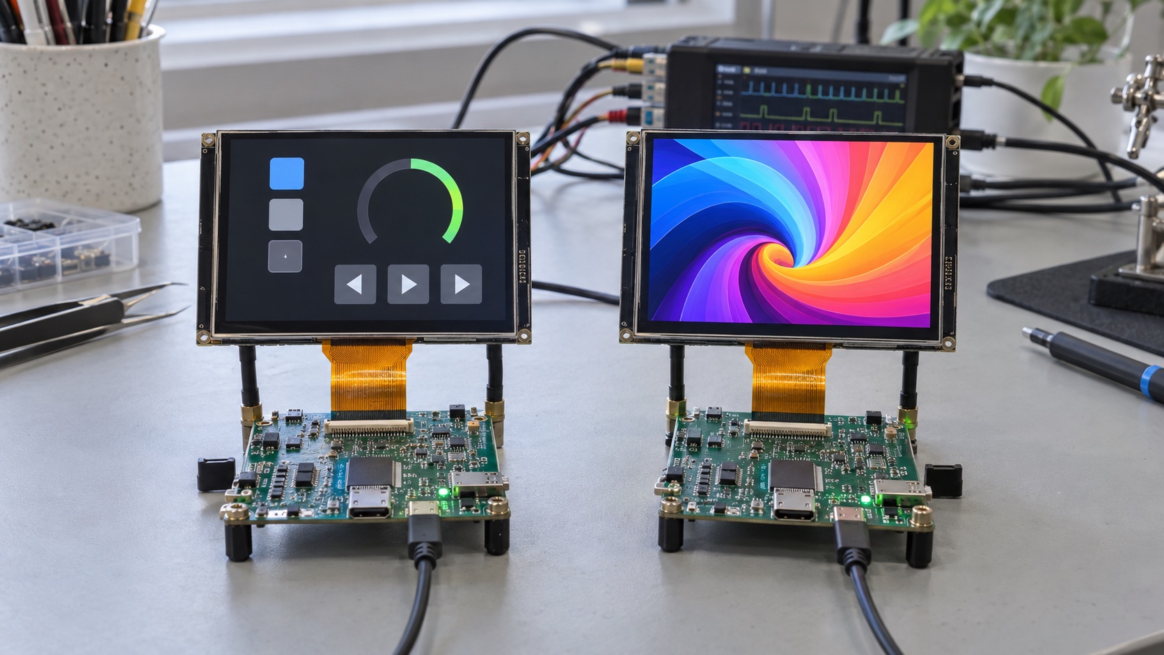
This comparison concerns conventional embedded DSI display integration. It does not assume that every feature in a DSI specification is implemented by a particular module. The hero is an AI-generated illustration of two evaluation setups, not a measured comparison.
Command Mode and Video Mode at a Glance
| Question | Command mode | Video mode |
|---|---|---|
| How do pixels arrive? | Image-write transactions to a supported controller | A scheduled stream associated with display timing |
| Where is a retained image commonly held? | Panel/controller GRAM | Host framebuffer; panel may have line buffers or other storage |
| Must unchanged content be sent every frame? | Often no, if panel operation supports retention | Normally yes during continuous streaming |
| Can a small region be updated? | Often, when address-window writes are supported | Rendering can be partial, but link scanout usually remains a full stream |
| Main synchronization problem | Avoid writing pixels at an unsafe scan position | Deliver pixels on time and switch host buffers safely |
| Power-saving opportunity | Reduce transfer activity for infrequent updates | Use supported blanking, clock, refresh, and sleep features |
| First compatibility check | Panel memory and command-image support | Required video submode, timing, and lane rate |
The MIPI Alliance DSI overview identifies DSI as the host-to-display interface using D-PHY and the Display Command Set. A module datasheet and host documentation are still needed to identify the available operating modes.
For broader interface selection, see MIPI vs LVDS vs RGB.
What Happens in Command Mode?
In a typical command-mode system, the host sets an image-write region and sends pixel data into display-controller memory. The panel then refreshes the glass from its stored image. If the screen is unchanged, the host may be able to stop sending pixel updates while the image remains visible.
The host still needs a rendering strategy. It may use a full framebuffer, multiple buffers, or smaller draw buffers that generate portions of the image. Panel GRAM does not automatically remove the host’s memory requirements or solve compositing and animation performance.
A useful workload is a status display whose numerical field changes occasionally while most of the layout remains static. Sending the changed region can reduce transferred data, provided the driver and panel support that region and alignment.
Partial Updates Need a Complete Software Path
Dirty rectangles must survive from the graphics library through the display driver to the actual DSI transactions. If middleware renders a small area but the driver always sends a full frame, the expected link saving disappears.
Check coordinate conventions, address-window boundaries, pixel packing, DMA alignment, and transfer completion. A reused draw buffer must not be overwritten while the peripheral is still reading it.
TE Is a Timing Signal, Not Extra Bandwidth
A tearing-effect signal or supported synchronization event can indicate an appropriate relationship to panel scanning. The exact meaning depends on configuration and panel capabilities.
Calculate whether the proposed region can be written within the permitted schedule. A full-frame transfer that is too slow will not become tear-free merely because it starts on a TE edge. See the screen-tearing guide for buffer ownership and synchronization checks.
What Happens in Video Mode?
Video mode sends a stream timed to the panel’s scan requirements. The host display controller commonly reads a framebuffer and delivers active image data, while the DSI host packages that stream for the serial link.
A panel that lacks retained full-frame storage cannot necessarily continue displaying a valid static image after its video stream stops. Its line buffering is not equivalent to command-mode GRAM. Follow its specified behavior for clock stopping, blanking, and sleep.
Video mode is often a natural fit for continuous animation or video, but it also requires dependable memory service. A valid serial lane rate does not prevent a host FIFO underrun if the framebuffer bus is starved by other activity.
Burst and Non-Burst Are Video Submodes
Common video configurations include burst mode and non-burst modes using sync pulses or sync events. They differ in how pixel packets and timing intervals are scheduled.
Burst operation can send a line’s pixels at a rate above the average pixel requirement and leave time for other permitted link states. Non-burst operation more closely follows the source video timing. Neither label establishes a universal bandwidth or power advantage: inspect the actual packet schedule, receiver buffering, and low-power transitions.
ST’s AN4860 DSI host application note includes command-mode and video-mode integration examples. Its small-display example uses panel GRAM, whereas its large-display example streams to a display without GRAM. Those examples illustrate why panel architecture comes before a host configuration choice.
DCS Commands Do Not Identify the Image Mode
A video-mode display may require commands to configure the controller, leave sleep, select a pixel format, or turn the display on. It can also permit some command transactions during video operation.
Likewise, “low-power command” and “command mode” are not interchangeable terms. LP and HS describe physical-link operating states; command and video modes describe how the display interface transfers image content. Supported combinations depend on the devices and transaction type.
During bring-up, prove these separately:
- Power and reset satisfy the module’s requirements.
- Required initialization commands reach the controller.
- The host and panel agree on the image-transfer mode.
- The pixel format and timing are correct.
- Image transfers complete without protocol or memory errors.
The MIPI DSI debug checklist provides the measurement sequence when initialization works but no image appears.
Compare Bandwidth Using the Real Workload
Consider an illustrative 480 × 800 RGB888 display. One uncompressed full frame contains:
480 × 800 × 3 = 1,152,000 bytes
Sixty complete image updates per second require 69.12 MB/s of pixel payload before packet and physical-link overhead. If a supported command-mode application updates only a 100 × 100 region ten times per second, that region’s pixel payload is 0.30 MB/s.
That is a large difference in payload, but it is not a prediction of equal battery savings. The panel still scans, the backlight still consumes power, and host rendering can dominate some workloads. Frequent full-screen animation may erase most of the transfer advantage.
Use the DSI lane-count and data-rate guide to convert the workload into a transfer-time budget. Use the portable-display power budget to compare energy at the battery input.
Choose a Mode With This Compatibility Checklist
Before selecting a panel, request a written answer for each item:
- Exact supported command/video modes and video submodes.
- Lane counts, lane-rate range, and clock behavior.
- Supported wire pixel formats and packing rules.
- Panel memory, partial-update constraints, and TE support.
- Approved initialization and sleep/wake sequences.
- Working support in the intended operating system or MCU driver.
- Behavior after host reset or interrupted image transfer.
A host specification stating “supports DSI” is insufficient. Its software stack may support fewer modes than its hardware, and a bridge may impose additional constraints.
Validate the Decision Before Freezing the Design
Test a static image, small-region changes, rapid scrolling, and full-screen animation. Record visible tearing, transfer duration, FIFO or protocol errors, input power, and wake latency at the intended brightness.
Repeat after sleep, warm restart, and a controlled power cycle. A design that works only after a cold boot may have a state-recovery problem rather than a mode-selection problem.
Keep the chosen mode and its rationale with the approved module record. The best choice is the one that the whole panel, host, driver, and workload can support predictably.
Frequently Asked Questions
What is the main difference between MIPI DSI command and video mode?
Command mode sends image updates to a compatible display controller, commonly with panel-side frame memory. Video mode sends a timed pixel stream that the display consumes continuously. The exact panel and host must both support the selected mode.
Does sending DCS initialization commands mean a panel uses command mode?
No. A video-mode panel can require DCS commands for reset recovery, sleep exit, brightness, or configuration. Initialization command traffic and the mode used to deliver image pixels are separate choices.
Is command mode always lower power?
No. It can reduce link activity when updates are infrequent and the panel retains the image, but panel memory, internal refresh, backlight, host rendering, and wake transitions still consume energy. Compare measured whole-system power for the intended workload.
Can I change a video-mode panel to command mode in software?
Only if the exact panel controller, module configuration, host, and driver support that operation. A host mode switch cannot add frame memory or capabilities that the panel lacks.
Does command mode eliminate screen tearing?
No. Writes can still overlap the panel's scanout. Use the supported TE or synchronization mechanism and ensure image transfers fit the permitted update schedule.