
How to Review a TFT LCD Mechanical Drawing
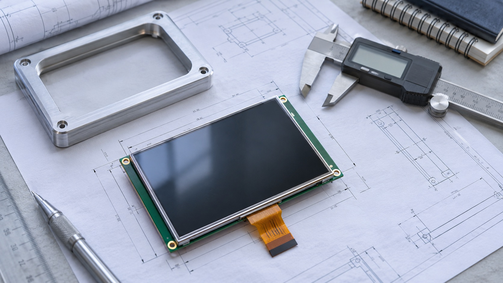
Review a TFT LCD mechanical drawing by connecting every critical dimension to the product’s datums, tolerance budget, assembly sequence, and inspection method. Nominal fit alone is insufficient. A production design must remain usable when permitted variations accumulate.
Start with Document Identity
Verify the complete part number, revision, units, drawing projection, and approval status. Check whether the drawing covers a bare LCD, touch assembly, bonded cover, or a module with a PCB. Match it to the quoted and sampled configuration.
The Newhaven module specification includes a drawing and revision history, illustrating why the PDF revision belongs in the project record. Do not scale a dimension from a screenshot when the drawing does not specify it; request clarification.
Establish One Coordinate System
Identify the module’s locating features and how the enclosure will constrain them. A dimension measured from an unused external edge may not control the assembled position. Align supplier and product drawings through intentional datums.
| Review item | Question | Evidence |
|---|---|---|
| Image position | Where is AA relative to locating features? | Dimensioned overlay |
| Window | Does the mask clear the image through tolerances? | Clearance budget |
| Outline | Is the maximum envelope accommodated? | Assembly section |
| Thickness | Are adhesive and protrusions included? | Stack drawing |
| FPC | Can it bend, mate, and remain strain-relieved? | Routing model |
| Mounting | Where may loads be applied? | Supplier-approved support |
| Touch | Are edges and intended controls qualified? | Assembled test |
Use AA versus VA versus module outline to resolve terminology before assigning enclosure dimensions.
Review the Optical and Mechanical Stack Together
The cover opening, printed black mask, sensor, adhesive, and LCD image must align. Their thicknesses also change the optical viewing geometry. Include front-view and off-axis checks so the mask does not clip useful content.
If a standard assembly cannot satisfy the stack, the custom TFT display module guide explains common changes to cover glass, FPC, backlight, and touch. Change only the elements needed to meet a defined requirement, then obtain an updated drawing.
Calculate Clearances at the Limits
Review minimum and maximum dimensions, not only nominal CAD surfaces. A hypothetical 0.5 mm gap can disappear when housing size, module position, and tape placement each move toward interference. Write down the chain and identify which variation belongs to which controlled part.
Check both clearance and appearance. An opening can have enough mechanical clearance yet expose an uneven border. Statistical tolerance analysis can be useful for suitable controlled processes, but it should not silently replace a required worst-case fit.
For each critical dimension, decide how it will be measured. A dimension inaccessible after bonding may need control earlier in the process. Reference samples can support appearance review, but numerical fit requirements should remain explicit.
Inspect the FPC in Three Dimensions
Confirm conductor contact side, pin-one position, pitch, thickness, stiffener, exposed contact length, and mating connector. “Same pin count” does not establish compatibility.
Model the insertion path and final bend. Avoid assuming that a cable can fold sharply at a stiffener or bond region. Request supplier bend guidance and check strain during enclosure closure and service access. Mechanical drawings should also identify keep-out regions around sensitive attachments.
A cable that is slightly too short can transfer load into a bond when the enclosure closes. One that is too long can be trapped under a support. Validate with the intended assembly order and representative parts.
Specify Load Paths and Bonding Areas
Locate support surfaces, gasket compression, adhesive placement, and screw-force paths. Avoid transmitting uneven enclosure loads through the active glass. Ask the supplier to approve uncertain support or pressure conditions.
Bond-line thickness, cleanliness, alignment fixtures, and cure requirements may affect both fit and optical quality. A successful hand-built sample does not establish that the same alignment can be repeated in volume.
Close the Review with Samples and Records
Run a fit trial using production-intent parts. Document bezel alignment, visible borders, insertion access, cable slack, touch corners, and any pressure-related image changes. Follow the incoming inspection checklist to translate approved features into receiving controls.
Resolve redlines before approving tooling. Keep a signed revision, overlay, unresolved-risk list, and sample identity together. When a later revision changes FPC position or cover dimensions, repeat the affected checks rather than relying on the previous approval.
A mechanical review is complete when the supplier, enclosure designer, assembly team, and inspector can all refer to the same controlled definition.
Hero image: AI-generated editorial illustration.
Frequently Asked Questions
What is the first drawing review check?
Verify part number, revision, units, assembly scope, and approval status before using dimensions.
Should fit be reviewed at nominal dimensions only?
No. Review minimum and maximum conditions and the full tolerance chain.
Why check FPC insertion paths?
A cable can fit in the final position while lacking safe access for assembly or service.