
Sunlight-Readable TFT Displays: Brightness and Contrast
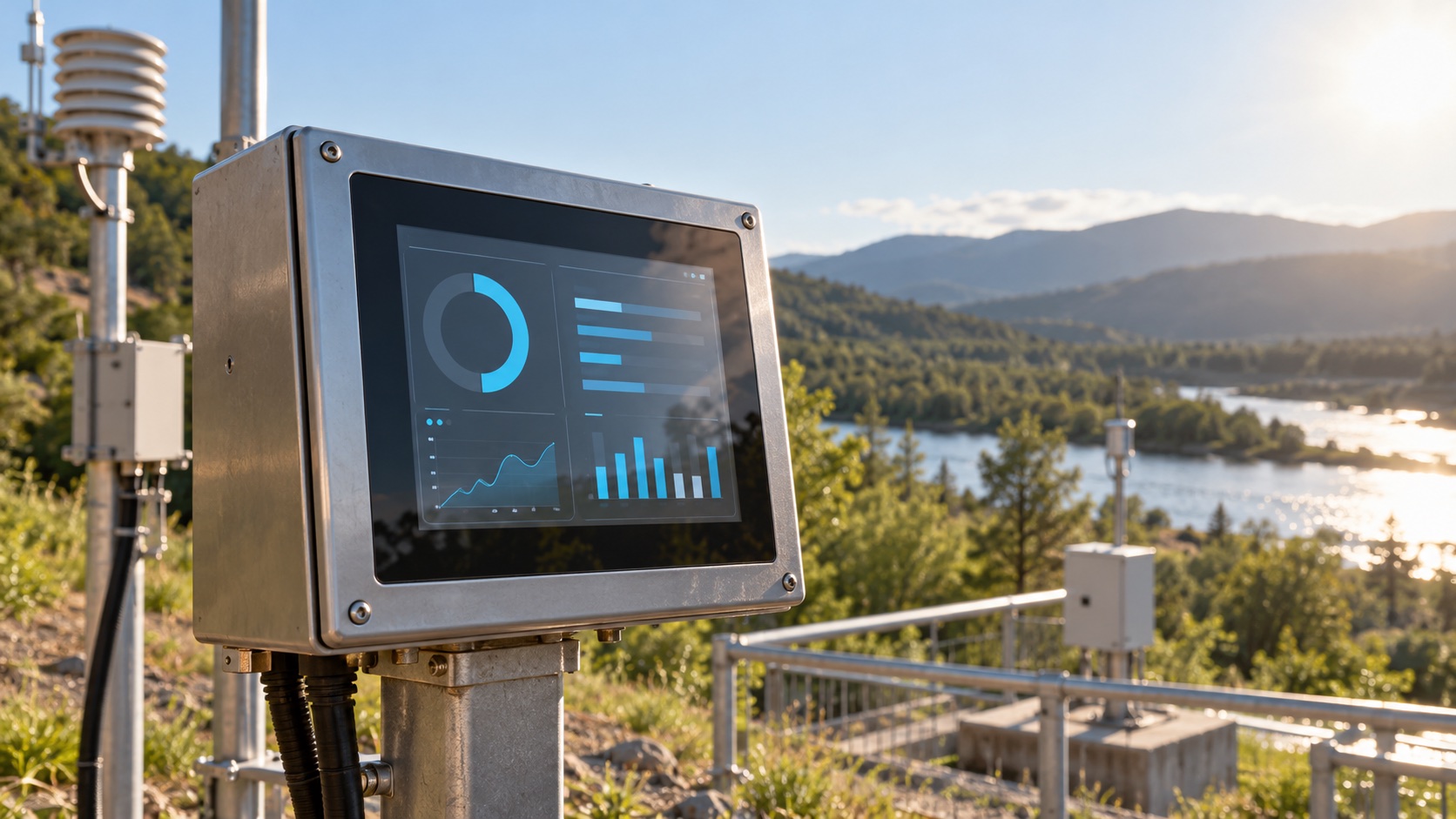
A sunlight-readable TFT needs enough image luminance and sufficiently low reflected light to preserve useful contrast at the user’s viewing position. A high backlight rating alone cannot establish readability. Evaluate the assembled display, including touch sensor, cover lens, bonding, coatings, enclosure, and thermal controls.
This guide provides a selection workflow for outdoor equipment, portable instruments, and exposed control panels. Calculations are illustrative, not measurements of a specific product. The Hero image is an AI-generated scene illustration.
Start With the Task and Lighting Geometry
Specify what the user must read: a large status icon, a small numeric value, a graph, or a dense configuration menu. These tasks have different requirements even on the same screen.
Record whether use occurs in open sun, under a canopy, through a vehicle window, or in changing shade. Include mounting angle, viewing distance, portrait or landscape orientation, and polarized sunglasses where relevant. A reflection aligned with the user’s eyes can obscure information even when the average ambient light is moderate.
| Requirement | Useful evidence |
|---|---|
| Lighting | Illuminance at the screen and source direction |
| Viewing position | Distance, angle, user height, and screen orientation |
| Visual task | Smallest text, important symbols, and acceptable reading time |
| Front stack | Cover lens, touch sensor, adhesive, coatings, and air gaps |
| Thermal conditions | Ambient temperature, solar exposure, and enclosure heat |
| Energy limits | Allowed continuous and peak display power |
Use the TFT module selection guide to combine these requirements with interface, mechanical, and supply constraints.
Nits and Lux Describe Different Quantities
A nit is one candela per square meter, a measure of luminance. Lux measures illuminance incident on a surface. You cannot convert a lux reading into a required nit value without knowing the surface’s reflection behavior and measurement geometry.
Ask whether the quoted luminance is measured at the bare LCD, after a touch panel, or through the final cover. Also ask for LED current, temperature, warm-up condition, and whether the value is typical or guaranteed minimum. An assembly’s optical losses can make a bare-panel figure misleading.
The brightness calibration guide explains how to keep measurement position and operating conditions consistent.
Ambient Contrast Explains Why Reflection Matters
A simplified model adds reflected ambient luminance to both white and black image levels:
Ambient contrast = (Lwhite + Lreflected) / (Lblack + Lreflected)
All three luminance terms must use the same units and viewing geometry. This approximation assumes the reflected contribution is similar in the two image states; it does not model every directional glare effect.
Consider an illustrative display with white luminance of 800 cd/m² and black luminance of 1 cd/m²:
| Condition | Reflected contribution | Calculated contrast |
|---|---|---|
| Dark measurement environment | 0 cd/m² | 800:1 |
| Strong reflection | 200 cd/m² | About 5.0:1 |
| Reflection reduced | 50 cd/m² | About 16.7:1 |
| White increased to 1200 cd/m², black held at 1 for comparison | 200 cd/m² | About 7.0:1 |
The values are chosen to isolate the trade-off, not to predict a particular coating. In a real LCD, raising backlight drive can also increase black luminance. The example shows why reducing reflected light may be more effective than increasing power alone.
Reduce Reflection Across the Whole Optical Stack
An air gap introduces interfaces that can reflect incident light. Optical bonding replaces a selected gap with an optically matched adhesive, changing those internal interfaces. Newhaven’s custom-display guidance describes bonding as a way to improve visibility by removing the display-to-cover air gap.
Bonding does not remove the outer air-to-cover interface or guarantee outdoor performance. Adhesive choice, voids, edge design, thermal expansion, and serviceability remain part of the engineering decision. See OCA bonding versus an air gap for the assembly trade-offs.
At the outer surface, consider AR and AG separately. Edmund Optics’ AR coating explanation describes reflection reduction and the importance of wavelength and incidence angle. Its optical principles are relevant here, but a display cover requires its own visible-spectrum, durability, and angle specifications.
Use the AR versus AG display guide to evaluate sharp reflections, diffuse haze, and image detail. A hood or a modest mounting-angle change can also reduce glare at the intended viewing position.
Check Heat and Power at Sustained Brightness
Higher LED drive adds electrical load and heat. A module that initially reaches the desired luminance may not maintain it after the enclosure and backlight warm up.
Measure the final assembly under the expected solar and ambient conditions. Record front-surface luminance, local temperatures, input power, and any automatic dimming or thermal limiting. Do not assume room-temperature brightness remains constant across the full operating range.
For battery equipment, compare the readability gain with the portable TFT power budget. For temperature specifications, distinguish operating and storage limits before choosing the panel.
Make the Interface Readable Too
Use adequate character size, strong foreground/background contrast, and redundant indicators for important states. Small low-contrast gray text can undermine a good optical design. Test the actual interface rather than only a full-white screen.
Check dark and light interface themes in the intended environment. One theme may work better for a specific reflection pattern, but there is no universal winner. Confirm that color-coded states remain distinguishable with sunglasses and at the required off-axis views.
Automatic brightness control should respond smoothly to transitions between shade and sun. Place the light sensor where it represents the screen’s exposure and avoid making the user’s hand or enclosure shadow dominate its reading.
A Repeatable Outdoor Evaluation
- Assemble the production-intent cover, touch stack, bezel, and display.
- Set documented brightness, interface content, and supply conditions.
- Record illuminance, light direction, viewing angle, and screen temperature.
- Measure white and black luminance at the intended viewing position.
- Evaluate the actual reading and touch tasks, including sunglasses.
- Repeat after thermal stabilization and during lighting transitions.
- Compare candidates under the same conditions and record limitations.
Photographs are useful records, but automatic exposure can make one screen look unfairly brighter than another. Lock exposure and geometry for comparisons, and retain instrument readings alongside the images.
Before procurement, agree on the complete-stack luminance requirement, optical construction, environmental conditions, and acceptance method. “Sunlight readable” becomes a useful purchasing requirement only when both parties can reproduce the same test.
Frequently Asked Questions
How many nits does a sunlight-readable TFT need?
There is no universal threshold. Required luminance depends on reflected ambient light, cover materials, viewing geometry, image contrast, and the user's task. Evaluate the complete assembly under the intended lighting rather than selecting by nits alone.
Does optical bonding make an LCD sunlight-readable?
Bonding can reduce reflections at internal air interfaces and improve ambient contrast, but the outer surface, backlight, viewing angle, and enclosure still matter. Verify the assembled display in its intended environment.
Is 1000 nits always better than 700 nits outdoors?
Not necessarily. A lower-luminance assembly with substantially less reflection can deliver better ambient contrast. Compare front-surface luminance and reflection under identical conditions, including thermal behavior.
Is anti-glare the same as anti-reflective?
No. Anti-glare treatments primarily redistribute reflections by scattering light, while anti-reflective treatments reduce reflected light over specified wavelengths and angles. Both can be useful, but they have different optical trade-offs.
Why does an outdoor display become dim after warming up?
Possible causes include thermal brightness limiting, driver or supply limits, and temperature-dependent optical behavior. Measure panel temperature, LED current, supply voltage, and luminance together before assigning a cause.