
Screen Tearing on TFT Displays: Causes and Fixes
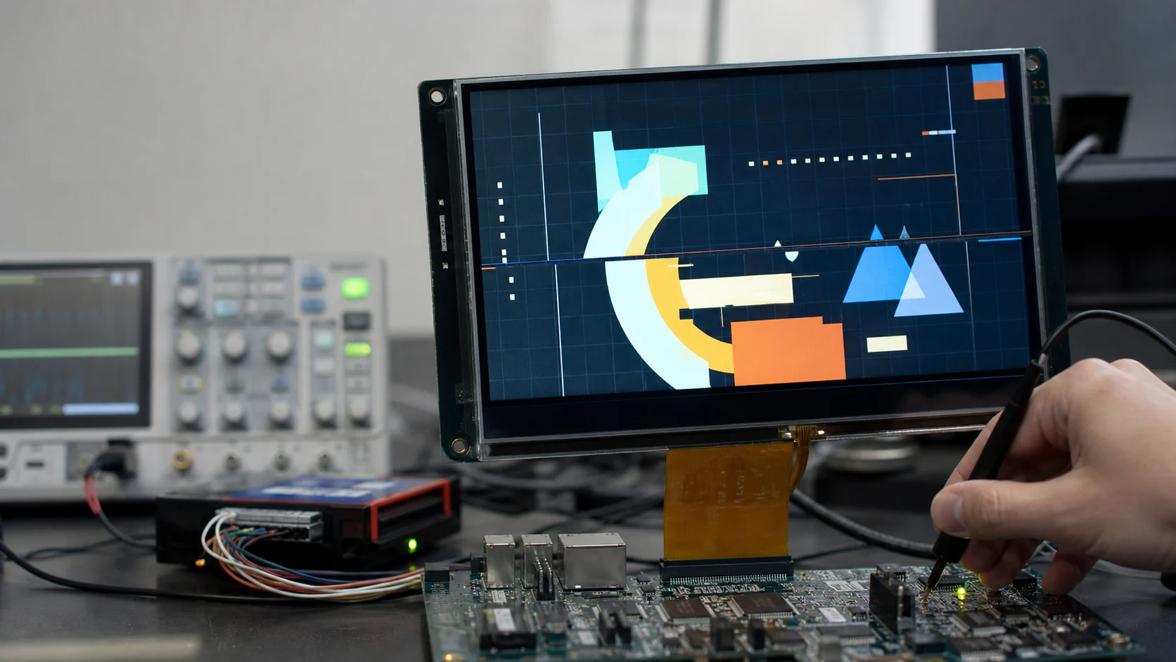
TFT screen tearing occurs when the display reads a frame while that same visible image is being changed. The screen then shows the top from one frame and the bottom from another, separated by a horizontal discontinuity. Fix it by rendering into a non-visible buffer and synchronizing the page flip or pixel transfer to VSYNC, vertical blanking, or the panel’s TE signal.
Tearing is a synchronization problem, not the same as flicker. Flicker changes brightness or image stability over time; tearing creates a spatial boundary between two valid image states. The distinction determines what to measure.
How to Recognize Screen Tearing
Use a full-screen animation with strong vertical edges, such as a rectangle moving horizontally. Tearing appears as one or more horizontal breaks where the upper and lower parts of the object are at different x-positions.
Other symptoms can look similar:
- Random horizontal lines: signal, power, or panel issue.
- Whole-screen jump: timing or buffer-address error.
- Flicker: repeated brightness/image loss.
- Motion blur/ghosting: LCD response-time limitation.
- Dropped frames: animation cadence issue without a split image.
For unstable lines and corrupted pixels, use TFT LCD lines and artifacts troubleshooting. For brightness or periodic instability, use the existing TFT flicker guide.
Why Tearing Happens
A display controller scans pixels from top to bottom at a fixed rate. If software modifies a visible framebuffer halfway through that scan, the already-scanned rows show old data and the remaining rows show new data.
The same concept applies to controller-based SPI/MCU displays. The panel scans its internal GRAM while the host writes new pixels into that memory. If the host update crosses the active scan, the screen can reveal a boundary.
Typical causes include:
- Rendering directly into the front buffer.
- Swapping front/back buffer addresses mid-frame.
- Starting DMA without waiting for vertical blanking.
- Updating panel GRAM without TE synchronization.
- Reusing a draw buffer before transfer completion.
- Incorrect flush-ready signaling in a graphics driver.
- Cache maintenance after, rather than before, the safe flip.
- Camera/video producer overwriting a buffer still being displayed.
Tearing Architecture Matrix
| Architecture | Where scan data lives | Common tearing cause | Preferred control |
|---|---|---|---|
| Raw RGB/LVDS framebuffer | MCU/SoC memory | Visible buffer updated mid-scan | Double buffer + VSYNC page flip |
| MIPI DSI video mode | Host framebuffer/video pipeline | Unsynchronized plane/frame update | Atomic/VSYNC-synchronized commit |
| SPI/8080 display with GRAM | Display controller memory | Host write overlaps panel scan | TE-synchronized transfer |
| Camera-to-LCD pipeline | Capture/display buffers | Producer and consumer share buffer | Buffer ownership + frame completion |
| Partial-update GUI | Draw/transfer buffers | Buffer reused before flush ends | Correct completion and dirty-area scheduling |
Step 1: Prove It Is Tearing
Create a repeatable motion test:
- Fill the background with a contrasting color.
- Move a tall rectangle horizontally at constant speed.
- Disable unrelated animations.
- Record with a high-frame-rate camera if the eye cannot locate the boundary.
- Compare tear position over many frames.
If the boundary moves when the update start time changes, tearing is likely. If a line remains at the same physical row even with a static image, investigate the panel or signal path instead.
Step 2: Map Every Buffer and Owner
Draw a data-flow diagram containing:
- Render buffer(s).
- Front/display buffer.
- Back buffer.
- DMA source and destination.
- Cacheable versus non-cacheable memory.
- Panel GRAM if present.
- Producer and consumer completion events.
For every buffer, define who may write, who may read, and which event transfers ownership. “Two buffers exist” is not enough; software must prevent rendering into the one currently scanned.
Step 3: Fix Single-Framebuffer Updates
With one framebuffer driving a raw RGB panel, any visible write can tear. Options are:
- Restrict updates to a vertical blanking interval when the work fits.
- Update only rows safely behind the current scan when scan position is known.
- Add a second full framebuffer.
- Render small regions into an off-screen draw buffer, then schedule controlled copies.
Vertical blanking is usually short. A full-screen software render rarely fits, which is why double buffering is the general solution for animated interfaces.
Step 4: Implement Double Buffering Correctly
Correct double buffering follows this sequence:
- Display controller scans front buffer A.
- Renderer creates the complete next frame in back buffer B.
- Cache/DMA work for B completes.
- Software requests a page flip.
- Display controller changes base address at VSYNC/vertical blank.
- Old front buffer A becomes the next back buffer.
Common mistakes:
- Changing the address immediately after rendering rather than at VSYNC.
- Starting a new render before the flip is acknowledged.
- Cleaning cache after the controller begins reading the buffer.
- Swapping a pointer in software but not updating the hardware layer register.
- Updating overlay layers at different frame boundaries.
Even double buffering can tear when the page flip and scan are not synchronized.
Step 5: Use VSYNC or a Line Event
For a raw RGB display controller, use its vertical-blank, VSYNC, reload, or line-event mechanism. The safe implementation is peripheral-specific, but the principle is consistent: program the new buffer address so it becomes active only at the frame boundary.
Measure the relationship between VSYNC and the buffer-address update with a GPIO marker or trace event. Do not infer synchronization only from average frame rate.
If several layers are composited, commit their addresses and properties atomically when the hardware supports it.
Step 6: Use the TFT Tearing-Effect Signal
Many SPI/MCU display controllers expose a TE output. Firmware may need to enable it and select vertical-blank-only or vertical-and-horizontal signaling.
A typical flow is:
- Wait for the configured TE edge.
- Start the pixel transfer in the allowed interval.
- Do not reuse the transfer buffer until DMA completes.
- If the transfer cannot finish in time, reduce the update area or frame rate.
The exact safe window depends on the controller, scan direction, interface speed, and TE mode. Follow the driver IC datasheet rather than assuming every TE edge means the same thing.
Step 7: Calculate Whether the Transfer Can Finish
For an uncompressed update:
Frame bytes = width × height × bytes per pixel
Approximate transfer time is:
Transfer time = frame bits / effective interface bit rate
Effective rate is lower than clock rate because commands, address setup, gaps, DMA overhead, and bus sharing consume time.
Example: a 480 × 272 RGB565 frame contains 261,120 bytes. At an ideal 40 Mbit/s, pixel data alone needs about 52 ms, before overhead. That cannot sustain a 60 Hz full-screen update. Partial updates, lower frame rate, a wider/faster interface, or a local framebuffer are needed.
Step 8: Verify Graphics-Library Flush Semantics
For a GUI library, confirm:
- Draw buffers remain valid until transfer completion.
- Flush-ready is signaled only after DMA/pixel transfer ends.
- Partial areas use the correct coordinates and stride.
- Two small draw buffers are not mistaken for two full framebuffers.
- Full/direct render modes match the hardware architecture.
- VSYNC/TE callback does not race with rendering.
Two draw buffers can improve throughput while still tearing if updates enter the visible GRAM at arbitrary scan phases. Buffer count and synchronization solve different problems.
Step 9: Check Cache, DMA, and Memory Bandwidth
Cache errors often create stale blocks or incomplete frames that resemble tearing. Before a display DMA/controller reads a rendered buffer, clean the relevant cache lines according to the MCU/SoC architecture. Keep buffer addresses, size, and cache-line alignment correct.
Also measure whether memory bandwidth supports simultaneous rendering, DMA2D/GPU, camera, and display scanout. Underflow can create repeated lines or blank regions rather than a clean tear. Separate it by checking controller underflow flags and testing with other bus masters disabled.
Step 10: Measure the Result
After the fix, test:
- Full-screen horizontal and vertical motion.
- Partial updates at several positions.
- Maximum animation load.
- Touch interaction during animation.
- Camera/video input if present.
- Lowest and highest supported refresh rates.
- Long-duration operation with other DMA and memory clients active.
Use a GPIO pulse at render complete, transfer start/end, VSYNC/TE, and page-flip acknowledgment. A four-channel capture makes race conditions visible.
Common Tearing Fixes That Do Not Fully Work
- Adding a second buffer without VSYNC-synchronized flipping.
- Increasing SPI speed beyond the panel or PCB margin.
- Delaying a fixed number of milliseconds instead of using TE/VSYNC.
- Calling flush-ready when DMA starts rather than when it finishes.
- Disabling cache globally rather than fixing coherency.
- Lowering animation rate while still writing the visible buffer.
- Hiding the tear line outside the active area instead of fixing ownership.
Prevention Checklist
- Choose the buffering architecture before finalizing memory size.
- Budget effective, not theoretical, interface bandwidth.
- Use explicit buffer ownership states.
- Synchronize page flips to VSYNC/vertical blank.
- Use the panel TE signal for GRAM updates when available.
- Keep render, DMA, cache, and flip completion separate.
- Log display underflow and missed-deadline counters.
- Retain a moving-bar tearing test in validation firmware.
Engineering References
- STMicroelectronics AN4861: LCD-TFT display controller on STM32 MCUs — framebuffer synchronization, DMA2D, bandwidth, and tearing behavior.
- LVGL display refreshing documentation — synchronizing refresh with VSYNC or TE and controlling refresh timing.
Apply the exact synchronization and cache rules for the display controller, graphics library version, RTOS, and panel driver used in the product.
Frequently Asked Questions
What causes screen tearing on a TFT display?
Screen tearing occurs when the display scans one frame while software or DMA changes the pixels being scanned. The visible frame then contains parts of two different images. Unsynchronized framebuffer writes, page flips, SPI transfers, or camera/video buffers are common causes.
Does double buffering always eliminate tearing?
No. Double buffering prevents rendering into the visible buffer, but the buffer address must still be swapped during a safe interval such as vertical blanking. A mid-frame page flip can tear even when two complete framebuffers are used.
What is the TE pin on a TFT display?
TE means tearing effect. On many controller-based TFTs, the TE output indicates a safe timing point or scan position so the host can synchronize pixel updates with the panel refresh. Its polarity, mode, and timing are controller-specific.
Can low SPI bandwidth cause screen tearing?
Low bandwidth does not automatically cause tearing, but a transfer that overlaps the panel scan can reveal the boundary between old and new data. Partial updates, a lower frame rate, a faster interface, TE synchronization, or a different buffering strategy may be required.
Why is the tear line always near the same position?
A repeatable tear position means the update begins at a consistent phase relative to the panel scan. Moving the update time or transfer duration moves the boundary. Synchronizing to VSYNC or TE should make the update occur in a controlled safe window.