
Wrong or Inverted Colors on a TFT Display
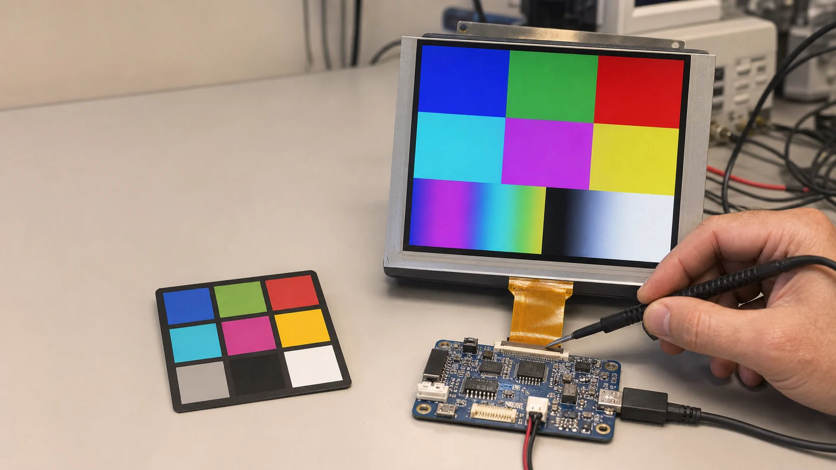
Wrong colors on a TFT display usually come from a mismatch in RGB/BGR order, pixel format, byte order, bus wiring, or controller configuration. Start with solid red, green, blue, white, black, and gray patterns. Those six frames identify whether the fault is a channel swap, missing bit group, inversion setting, packing error, or broader optical/calibration issue.
Do not start by adjusting gamma. Gamma tuning cannot repair swapped red and blue channels or an RGB565 byte-order error. First prove that digital pixel values reach the correct physical color channels.
Identify the Type of Color Error
| Symptom | Likely cause | First test |
|---|---|---|
| Red appears blue and blue appears red | RGB/BGR order or swapped bus groups | Solid red and solid blue |
| Colors look neon or unrelated | RGB565 byte swap/format mismatch | Known 16-bit color constants |
| One channel is missing | Disconnected bus bits, pin mapping, format | Full-intensity R/G/B frames |
| Image looks like a negative | Inversion command or software inversion | Toggle inversion with static data |
| Correct hue but posterized gradients | Reduced color depth, missing LSBs, bad dithering | Per-channel ramps |
| Washed-out blacks and low contrast | Limited/full range, gamma, panel mode, optics | Black/gray ramp and direct framebuffer |
| Colors change with motion or clock | Setup/hold, bandwidth, signal integrity | Reduce speed within specification |
| Solid fills correct, photos wrong | Decoder, color-space conversion, alpha/palette | Compare generated and decoded pixels |
If the display also has fixed lines or repeating blocks, begin with TFT LCD lines and artifacts troubleshooting. If it is entirely white, use the white-screen checklist.
Step 1: Generate Colors in Code
Avoid photographs and compressed assets for the first test. Write exact pixel values directly into the framebuffer or display controller:
| Intended color | RGB888 | RGB565 |
|---|---|---|
| Black | 0x000000 | 0x0000 |
| White | 0xFFFFFF | 0xFFFF |
| Red | 0xFF0000 | 0xF800 |
| Green | 0x00FF00 | 0x07E0 |
| Blue | 0x0000FF | 0x001F |
These values assume conventional RGB ordering. If the display shows blue for the RGB565 red value, either the system expects BGR order or red/blue paths are exchanged.
Also generate 25%, 50%, 75%, and 100% ramps for each channel. Ramps reveal stuck bits and bit significance that full-intensity colors can hide.
Step 2: Check RGB Versus BGR Order
Color order can be controlled in several places:
- Panel initialization register or memory-access-control command.
- Host display-controller output configuration.
- Graphics-library color format.
- Framebuffer pixel layout.
- Physical RGB bus mapping.
Change only one layer. If both software and panel configuration swap red and blue, the two mistakes may cancel during one test and return after a library update.
For a parallel RGB interface, trace R, G, and B groups from the host pinout to the panel connector. For SPI/MCU panels, inspect the controller command that selects RGB/BGR order. For MIPI DSI, confirm the negotiated/configured pixel format and how the bridge or host packs components.
The MIPI, LVDS, and RGB comparison explains where serialization and mapping occur in each architecture.
Step 3: Verify Pixel Format End to End
Common formats include:
- RGB565: 5 red, 6 green, and 5 blue bits in 16 bits.
- RGB666: 6 bits per component, often transported in 18 or loosely packed 24 bits.
- RGB888: 8 bits per component in 24 bits.
- ARGB8888: 8-bit alpha plus RGB components in a 32-bit memory word.
Names alone do not define byte order in memory. A 32-bit CPU, DMA engine, display controller, and byte-oriented SPI link can each view the same bytes differently.
Document the path with a single red pixel:
- Numeric pixel value produced by software.
- Byte sequence stored in memory.
- Byte sequence read by DMA or the display peripheral.
- Byte/bit sequence transmitted on the interface.
- Format expected by the panel controller.
A logic analyzer is especially useful for SPI. Capture a short row of known pixels and decode the byte order rather than guessing at an endian setting.
Step 4: Check RGB565 Byte Swap
For RGB565 red (0xF800), memory on a little-endian CPU commonly contains bytes 00 F8. A byte-oriented display interface may expect F8 00. If those bytes are sent in the wrong order, color bits cross component boundaries and the result looks unrelated to the intended color.
Do not fix the symptom by redefining application color constants. Correct the conversion or transport boundary so every image, widget, and asset follows one format.
Graphics libraries may provide a byte-swap option or a flush-time conversion. Confirm the option matches the library version and the actual display driver.
Step 5: Audit Physical Bus Mapping
For 18- or 24-bit parallel RGB, compare every connected data bit with the panel pin table. Look for:
- R and B groups exchanged.
- Reversed bit order inside a channel.
- LSB/MSB confusion on reduced-width buses.
- One color bit shorted, open, or assigned to another peripheral.
- Incorrect alternate-function pin configuration.
- Level translator channels crossed.
Use channel ramps and walking-bit patterns. If enabling one framebuffer bit changes an unexpected color or intensity, follow that bit through the schematic, package pin, PCB, and FPC.
Step 6: Test Inversion Commands Separately
Many TFT controller ICs provide display inversion on/off commands. These commands relate to how the LCD is driven and are not the same as calculating 255 - pixel_value in software.
Use a fixed test image and toggle only the documented inversion command. If one state produces correct polarity and the other looks abnormal, retain the supplier-approved setting. Do not assume that command values are identical across related controller ICs.
If the image becomes a perfect digital negative regardless of panel command state, inspect rendering, image preprocessing, palette generation, and blending code.
Step 7: Check Pixel-Clock Edge and Signal Margin
An RGB panel samples color data relative to the pixel clock. If the host changes data on the edge the panel uses to sample, setup/hold margin can collapse. The screen may show unstable colors, colored speckles, or errors that change with temperature and cable length.
Compare clock polarity with the datasheet and measure at the FPC. Reduce pixel clock within the allowed range as a diagnostic test. If errors diminish, review timing, edge rate, series damping, routing, return path, and receiver thresholds.
Stable red/blue exchange is not normally caused by clock margin; random or temperature-sensitive color errors can be.
Step 8: Isolate the Graphics Pipeline
If direct solid fills are correct but decoded images are wrong, the display path is probably functioning. Check:
- Image source color space and ICC assumptions.
- RGB versus BGR decoder output.
- JPEG/PNG conversion into the target pixel format.
- Palette indices and palette byte order.
- Alpha premultiplication and blending order.
- DMA2D/GPU input and output formats.
- Row stride and alignment.
- Asset conversion tools used during the build.
Read back or dump a small framebuffer region and compare the bytes with expected values. This turns a visual judgment into a reproducible software test.
Step 9: Separate Digital Errors from Optical Differences
When primary colors and ramps are digitally correct, remaining differences may come from:
- Panel color gamut and white point.
- Backlight spectrum.
- Gamma curve.
- Viewing angle and panel mode.
- Cover lens, adhesive, or optical coating.
- Temperature and production tolerance.
Those are calibration and component-selection issues, not bit-order faults. Use a colorimeter and controlled test patterns as described in the display calibration workflow and color-temperature matching guide.
Known-Good Comparison Strategy
Compare four combinations where possible:
- Known-good software and known-good board/module.
- New software on known-good hardware.
- Known-good software on suspect hardware.
- Suspect module on known-good board.
Keep color test patterns identical. If the error follows software, inspect formats and conversion. If it follows one PCB, inspect mapping and timing. If it follows one module while the digital interface is correct, review panel variant, initialization, or module fault.
Common Color-Debugging Mistakes
- Adjusting gamma before verifying primary channel order.
- Using photos instead of exact generated colors.
- Assuming RGB565 defines transport byte order.
- Swapping both software and panel settings, hiding the root cause.
- Ignoring physical bit order on 18/24-bit buses.
- Changing interface clock and color configuration together.
- Treating viewing-angle color shift as digital corruption.
- Comparing displays at different brightness and ambient light.
Prevention Checklist
- Put solid fills, ramps, checkerboards, and walking bits in factory diagnostics.
- Document pixel format at every graphics and transport boundary.
- Add compile-time assertions for framebuffer bytes per pixel and stride.
- Review RGB bus mapping against both host and panel pin tables.
- Archive the exact driver IC initialization sequence.
- Capture interface data for one known row during bring-up.
- Use controlled brightness and measurement geometry for color acceptance.
- Re-run color tests after library, compiler, DMA, or panel revisions.
Engineering References
- STMicroelectronics AN4861: LCD-TFT display controller on STM32 MCUs — framebuffer color formats, pixel-format conversion, data mapping, timing, and bandwidth.
- LVGL display overview — display color format, color depth, draw buffers, and flush-driver responsibilities.
Use the documentation for the actual graphics library version, host peripheral, bridge, driver IC, and TFT panel in the product.
Frequently Asked Questions
Why are red and blue swapped on my TFT display?
The host and panel probably disagree about RGB versus BGR component order, or the physical red and blue bus groups are swapped. Display solid red and blue frames, then correct the controller's color-order setting, initialization command, or wiring.
Why do RGB565 colors look completely wrong?
Common causes are swapped bytes, the wrong 16-bit format, incorrect endianness, treating RGB565 as BGR565, or sending 18/24-bit data while the panel expects 16-bit. Verify the exact bit layout and the order bytes are transmitted.
What is the difference between color inversion and negative colors?
Some LCD controllers support a display-inversion command that changes pixel drive polarity behavior and can alter the apparent image if configured incorrectly. A photographic negative effect may also be caused by software inverting pixel values. Test controller inversion commands separately from framebuffer data.
Can wrong sync polarity cause wrong colors?
Usually sync problems affect geometry or stability, but an incorrect pixel-clock sampling edge or marginal setup/hold timing can capture incorrect color bits and appear as color noise. Stable channel swaps are more likely format or wiring errors.
Why are colors correct in solid fills but wrong in images?
If generated solid colors are correct, inspect image decoding, palette conversion, alpha blending, color space, stride, and asset preprocessing. The display hardware may be correct while the graphics pipeline supplies incorrectly converted pixels.