
TFT LCD Power-On and Power-Off Sequencing Guide
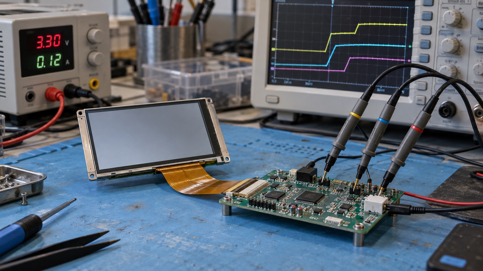
TFT LCD power sequencing is the controlled order of supply rails, reset, interface activity, initialization, and backlight enable. Start with the exact module’s timing diagram: there is no universal rail order or delay that works for every TFT. A reliable design also defines shutdown, brownout recovery, and rapid restart, not just the first successful boot.
This guide covers embedded TFT modules using RGB, SPI/MCU, LVDS, or MIPI DSI interfaces. It is a design and verification workflow; the examples are illustrative, not a replacement for the panel specification. The hero image is an AI-generated laboratory illustration, not a photograph of a completed validation test.
Identify Which Supplies the Host Actually Controls
A module connector may expose only one logic supply and separate LED terminals, or it may require several externally generated bias rails. Do not infer the architecture from screen size, resolution, or connector pin count.
| Function | Common names | What to establish |
|---|---|---|
| Digital core and I/O | VDD, VCC, IOVCC | Voltage range, ramp limits, and allowed pin levels while off |
| Source and gate drivers | AVDD, VGH, VGL | Whether generated internally and any mandatory ordering |
| Common electrode | VCOM | Buffer or internal generation, adjustment restrictions |
| Hardware controls | RESET, DISP, ENABLE | Active level, pulse width, and state during rail transitions |
| Pixel interface | RGB, SPI, LVDS, DSI | When clocks, data, and commands may start or stop |
| Backlight | LEDA/LEDK, BL_EN, PWM | Constant-current drive and permitted enable timing |
Use the TFT LCD datasheet reading guide to build a controlled specification sheet. Record the part-number suffix, drawing revision, driver IC, and initialization-table version. Similar-looking modules may require different startup behavior.
As one concrete example, the Newhaven 4.3-inch module specification includes a dedicated power-on/off sequence alongside its electrical and interface timing information. Its requirements apply to that module, not to every 4.3-inch TFT.
Turn the Datasheet Into a Timing Contract
For every delay, record both endpoints. “Wait 20 ms” is incomplete unless it states whether the timer begins at regulator enable, a voltage threshold crossing, power-good assertion, or reset release.
Create a table with these fields:
- Event and signal polarity.
- Required preceding event.
- Minimum and maximum interval, where specified.
- Measurement point at the module connector.
- Firmware or hardware owner.
- Behavior if the preceding event fails.
For an illustrative panel, suppose a specification requires at least 10 ms from supply stabilization to reset release and at least 5 ms from reset release to the first command. The earliest first command is 15 ms after stabilization. It is not necessarily 15 ms after the regulator-enable GPIO changes, because supply ramp and settling take additional time. These numbers explain the method; they are not recommended settings.
Avoid replacing minimum delays with arbitrary large delays. A longer wait may hide a race, violate a maximum interval, or lengthen boot without fixing rail order. Use the documented limits and margin justified by clock accuracy, scheduler behavior, and measured settling.
A Practical Startup State Machine
The following states are a useful software structure. Their order and transitions must be adapted to the module’s requirements.
1. Establish Safe Off-State Pin Levels
Keep the backlight disabled. Set reset and interface pins to their documented off-state levels before enabling supplies. Check what the MCU pins do during reset and bootloader execution, not just after the application configures them.
A high output connected to an unpowered display can feed current through protection structures. Level translators, pull-ups, and touch-controller interrupt lines can create additional back-power paths. Evaluate their partial-power behavior rather than assuming a disabled regulator means an unpowered panel.
2. Enable and Confirm the Required Rails
Apply the specified rail order and ramp behavior. When available, use power-good feedback with a timeout; otherwise validate a fixed delay against worst-case startup measurements. A control-register write confirms only that software requested power.
If external bias rails are required, coordinate their dependencies with the bias IC. The TI TPS65150 product documentation provides an example of a bias device with adjustable sequencing for negative and positive gate supplies. Such flexibility is a way to meet a panel requirement, not a universal sequence recommendation.
See AVDD, VGH, VGL, and VCOM explained for the distinction between these functions and the LED backlight supply.
3. Apply Reset and Initialization
Meet the reset pulse width, release delay, and input-level limits. Then send the approved initialization sequence if the module requires commands. Preserve vendor-specified delays between reset, sleep exit, register loading, and display enable.
Do not transplant an initialization table merely because another panel uses the same controller family. Glass configuration, scan direction, power settings, and firmware revision can differ. Raw RGB modules may instead depend mainly on hardware control pins and continuous video timing.
4. Make a Valid Image Available
Initialize the framebuffer before scanout or memory transfer begins. Confirm pixel format and interface timing. A black buffer is a useful startup image, but its bytes must match the configured format and memory stride.
For streaming interfaces, wait for the documented stabilization condition. For a command-mode panel, complete the initial image transfer and any required synchronization. Do not treat “DMA started” as “the panel has received the frame.”
5. Enable the Backlight
Enable the current driver only after the image path is ready and the required panel delay has elapsed. Ramp brightness if the product needs a gentle visual transition, while staying within the driver’s dimming constraints.
Keeping this as an explicit state makes a boot flash easier to diagnose: determine whether the backlight arrived early, the first frame was uninitialized, or the panel was reset after illumination.
Design Shutdown as a Separate Sequence
Normal shutdown often begins by dimming or disabling the backlight. The remaining steps depend on the panel: display-off commands, sleep entry, reset assertion, clock removal, and rail discharge may have specific relationships.
Do not stop clocks too early if the panel needs them to finish a shutdown operation. Conversely, do not continue driving data into an unpowered receiver unless the hardware explicitly permits it.
If the system can lose input power without warning, firmware may not have time to execute the normal path. Define what the hardware can guarantee during a collapsing supply. Required hold-up time and discharge behavior must come from the product’s power architecture and the panel specification.
Brownouts and Rapid Restarts Need Their Own Tests
An MCU reset does not necessarily reset the display. A display reset does not necessarily discharge its rails. Treat these as separate events.
| Test condition | Evidence to capture | Typical issue exposed |
|---|---|---|
| Cold boot at minimum input voltage | Rail ramps, reset, current | Slow startup or missed power-good |
| Warm restart without power removal | Reset pulse and command history | Panel retains incompatible state |
| Brief input interruption | Rail minimums and recovery | Partial brownout or back-power |
| Rapid off/on cycle | Residual rail voltage and off interval | Incomplete discharge |
| Sleep and wake | Clock state, commands, first frame | Incorrect resume sequence |
| Maximum backlight load at startup | Logic rail droop and LED current | Shared-supply overload |
Use a repeatable trigger and capture enough pre-trigger history to identify the initiating event. For a white field after startup, continue with the TFT white-screen checklist; for a visible image without illumination, use the backlight troubleshooting guide.
What to Measure at the Bench
Probe supplies at the module side of the connector. Use suitable probe grounding and voltage ratings, especially for negative gate bias. Avoid grounding a conventional scope probe to a non-ground node.
Capture at least the controlling rail, reset, backlight enable, and one indication of image activity. If channel count is limited, repeat the same triggered event while retaining a common reference signal. Record steady-state levels, overshoot, ramp time, inter-rail delay, and discharge time.
Repeat across the intended input-voltage and temperature range and on more than one sample. The acceptance criterion is that the specified limits remain satisfied, not that a single unit boots ten times on a warm desk.
Release Checklist
Before approving the design, retain the module revision, timing contract, firmware state diagram, startup and shutdown captures, brownout results, and known-good initialization file. Include recovery behavior for a failed rail or command transaction.
A robust sequencing design makes every transition explainable: what is powered, what the panel is allowed to receive, and when the user can see the image. That evidence is more useful for production support than a long unexplained delay in the boot code.
Frequently Asked Questions
What is the correct TFT LCD power-on sequence?
Use the sequence specified for the exact module. A common design holds the backlight off, establishes the required rails, applies reset, completes initialization, supplies a valid image, and then enables the backlight. Rail order, reset levels, clock requirements, and delays are panel-specific.
Should the backlight turn on before LCD data?
Keeping the backlight off until the LCD has a valid image usually prevents visible white flashes or random pixels. Some modules impose additional timing constraints, so coordinate backlight enable with the panel's documented startup sequence.
Can I use the power-on sequence in reverse for shutdown?
Not automatically. Some panels require a display-off or sleep command, continued clocks for a delay, a particular rail-removal order, or a minimum off interval. Implement the specified shutdown sequence separately.
Why does an LCD fail only after a quick restart?
Residual charge, back-power through signal pins, a missing reset pulse, or an insufficient minimum off time can leave the panel in an undefined state. Capture the power rails, reset, and interface pins through the entire restart.
Does a working backlight prove that panel power is correct?
No. The LED driver and the LCD logic or analog supplies may be separate. Measure each required rail at the module connector and verify its timing as well as its steady-state voltage.