
TFT LCD White Screen: Causes and Step-by-Step Troubleshooting
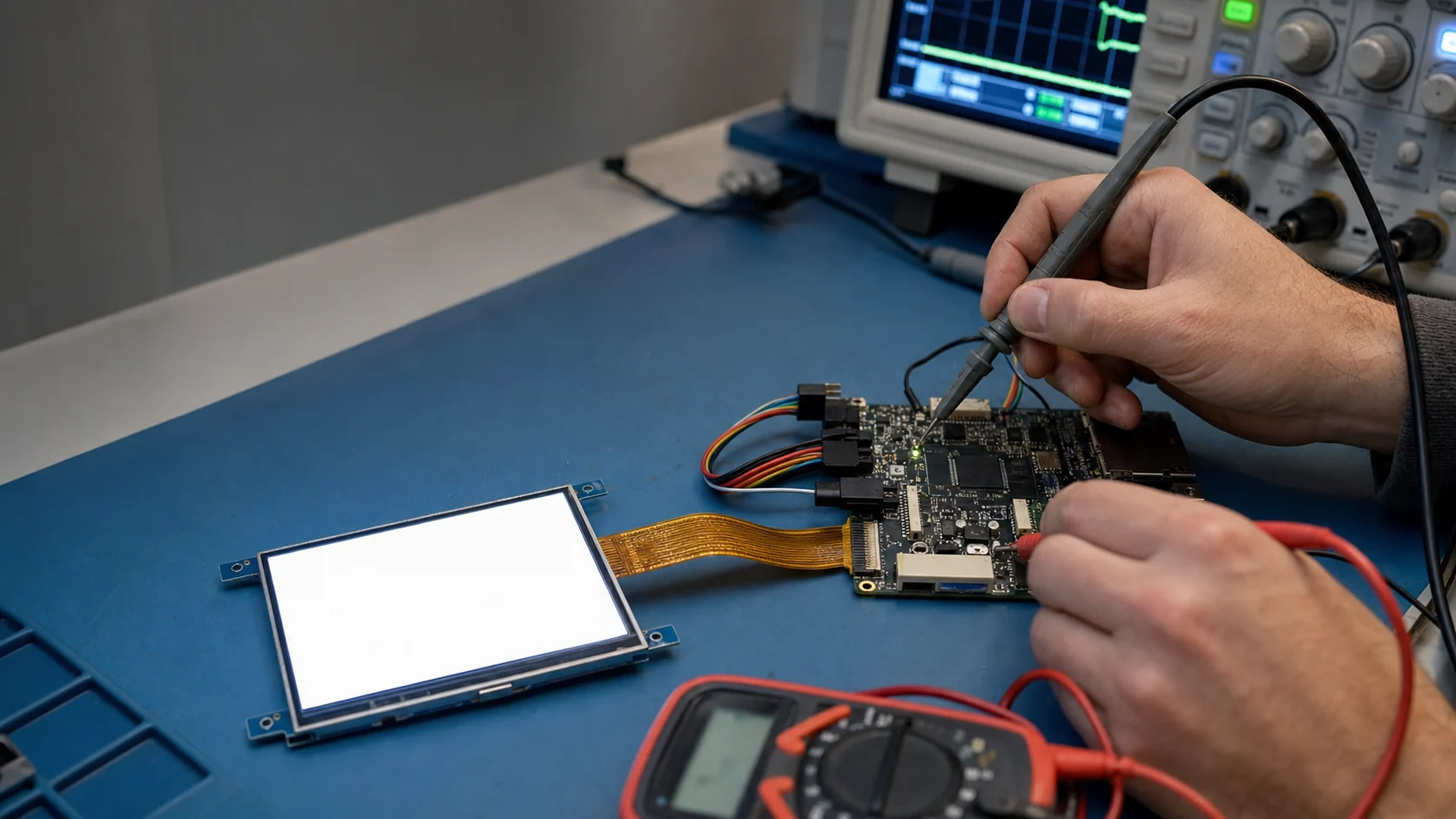
A TFT LCD white screen usually means the backlight is operating but the display pixels are not receiving valid power, initialization, timing, or image data. Check the module power rails first, then reset and enable signals, interface activity, initialization commands, FPC continuity, and finally the panel itself. Do not replace the LCD until those upstream checks are complete.
That answer applies to most embedded TFT systems, but “white screen” is a symptom rather than a diagnosis. A raw RGB panel, an SPI display with internal GRAM, and a MIPI DSI module can all look white for different reasons. The fastest repair comes from identifying which part of the display chain is already working.
What a White TFT Screen Tells You
Most transmissive TFT LCDs look bright when the LED backlight is on and the liquid-crystal layer is not producing the intended image. Therefore, a stable white field usually confirms only one thing: light is passing through the stack.
It does not confirm that these functions are working:
- LCD logic supply and internal analog rails.
- Driver IC reset and startup state.
- Display enable or sleep-out command.
- RGB pixel clock, sync, data enable, or pixel bus.
- SPI/MCU commands and framebuffer writes.
- MIPI DSI low-power commands or high-speed video packets.
- FPC contacts between the host and module.
If the screen is dark rather than illuminated, use the companion guide for an LCD with an image but no backlight. If the display shows fragments, lines, or moving noise, go to TFT LCD lines and artifacts troubleshooting.
White Screen Symptom Matrix
Use the behavior around the white screen to narrow the fault before probing.
| Observed behavior | Most likely area | First check |
|---|---|---|
| White immediately at power-on and never changes | Power, reset, enable, initialization | Measure rails and reset at the FPC |
| White until firmware starts, then still white | Interface or init sequence | Confirm commands, pixel clock, DE and data |
| Brief correct image followed by white | Power droop, sleep/reset event, software crash | Scope rails and control signals during failure |
| Image appears when FPC is pressed | Connector, cracked trace, poor contact | Inspect connector lock and continuity |
| White only after warm-up | Marginal rail, connector, driver IC or panel | Temperature-correlate voltage and signal changes |
| White on one sample only | Module/FPC fault or variant mismatch | Compare label, revision and known-good sample |
| All samples white on one PCB revision | Board pinout, power or firmware | Compare schematic and layout with datasheet |
Before Measuring: Freeze the Configuration
Record the exact LCD part number, datasheet revision, PCB revision, firmware build, initialization table, and symptom timing. Display families often have nearly identical mechanical parts with different pinouts, driver ICs, scan directions, or startup commands.
Also save photographs of the module label and connector orientation. Pin 1 errors, bottom-contact versus top-contact connectors, and mirrored FPC drawings are common enough to deserve an explicit check.
The TFT LCD datasheet guide explains how to separate controlled limits from typical values before debugging.
Step 1: Prove the Backlight Is the Source of the White Field
Reduce or disable the backlight while keeping the LCD logic powered. If the bright white field disappears with backlight current, the LED path is working. If the surface still looks white only because of room light, the original symptom may actually be “no backlight and no confirmed image.”
Check that backlight current is within the module rating. An overdriven backlight can distract from an unpowered LCD and may damage the LEDs during extended debugging.
Step 2: Measure Every Required Power Rail
Measure at the display connector, not only at the regulator output. Connector resistance, FPC damage, load switches, ferrite beads, and sequencing circuits can create a correct board-side voltage but a missing module-side voltage.
Depending on the module, required rails may include:
- Logic or I/O supply such as
VDD,VCC, orIOVCC. - Analog source-driver supply such as
AVDD. - Gate-on and gate-off rails such as
VGHandVGL. - Common-electrode voltage such as
VCOM. - Separate touch-controller supply.
- LED backlight supply and regulated current.
For a module that generates internal rails, verify the input supply, enable state, and startup current. For exposed rails, compare polarity and min/typ/max values with the exact datasheet. A missing negative VGL rail, for example, cannot be evaluated as though it were a positive logic supply.
Use an oscilloscope for startup and failure events. A multimeter may show a normal average voltage while missing a short brownout that resets the panel.
Step 3: Check Reset, Enable, and Power Sequence
Probe reset at the module pin. Confirm:
- The active polarity is correct.
- The pulse reaches the required level.
- The pulse width meets the minimum.
- Reset is released only after the required rails are stable.
- Commands or video begin after the specified delay.
Then check DISP, ENABLE, standby, sleep, or shutdown pins. A floating pin may work on one prototype and fail on another. Do not rely on undocumented internal pulls.
Power-off behavior matters too. If the host continues driving interface pins after the LCD supply is removed, current can flow through protection structures and leave the panel in an undefined state. A full discharge followed by a controlled cold start is a useful comparison with a software reset.
Step 4: Verify Initialization for Controller-Based Displays
SPI, MCU, and many MIPI DSI panels need a command sequence before they can display pixels. Log the sequence and compare it byte for byte with the driver IC documentation and supplier sample code.
Check for:
- Hardware reset followed by the required delay.
- Software reset, sleep-out, and display-on commands.
- Pixel format and color depth.
- Memory access control, scan direction, and RGB/BGR order.
- Porch, gate, power, gamma, VCOM, and frame-rate settings.
- Required delay after sleep-out before display-on or pixel data.
- Command/data selection and chip-select timing.
- Correct DSI virtual channel, packet type, and low-power command mode.
Do not assume code for a related driver IC is interchangeable. Suppliers sometimes approve an “equivalent” IC with a different initialization table.
For debugging, read back an ID or status register when the interface supports it. A valid read proves more than seeing transmitted bytes on the host pin because it confirms a round trip through the connector and controller.
Step 5: Confirm Interface Activity at the Module
Parallel RGB display
Use an oscilloscope or logic analyzer to confirm pixel clock, data enable, HSYNC, VSYNC, and several color bits at the FPC. Compare clock frequency, polarity, active width, porches, and totals with the datasheet.
Force solid red, green, blue, black, and white frames. Solid patterns make swapped or missing color groups easier to identify and reduce uncertainty from application graphics.
If there is no pixel clock or data enable, stay on the host/controller side. If all signals are present at the host but absent at the FPC, inspect routing, level translation, series resistors, and connector continuity.
SPI or 8080/6800 MCU display
Confirm chip select, clock/write strobe, data/command, reset, and data lines. Make sure the framebuffer window is defined before pixel writes and that the byte count matches the selected color format.
A display can accept commands yet remain white if pixel data never arrives, the address window is zero-sized, or the controller remains asleep.
LVDS or MIPI DSI display
Check that the host and panel agree on lane count, mapping, clock mode, pixel format, video mode, and timing. Inspect error/status registers before changing random PHY parameters. The dedicated MIPI DSI debug checklist covers this path in detail.
Step 6: Inspect the FPC and Connector
Power down before reseating the cable. Look for:
- Incomplete insertion or an open locking bar.
- FPC contacts facing the wrong side.
- Bent connector contacts or contamination.
- Creases through copper traces near the stiffener.
- Excess bend, pull, or torsion from the enclosure.
- Misaligned fine-pitch FPC after repeated rework.
- Cracked solder joints at the board connector.
Use continuity measurements only with power removed and with awareness of parallel paths through IC protection structures. The FPC layout and pin-mapping guide provides design rules for avoiding recurring cable faults.
Step 7: Separate Hardware from Software
Use controlled substitutions instead of changing several variables at once:
- Known-good panel on the suspect board.
- Suspect panel on a known-good board.
- Supplier evaluation board with the same panel revision.
- Minimal firmware that displays static color bars.
- Known-good initialization table and conservative timing.
Interpret the result as a matrix. If every panel fails on one board, focus on the board or firmware. If one panel fails on multiple known-good boards, focus on the module. If the failure follows one firmware build, compare initialization, clocks, pin multiplexing, memory, and power-control changes.
Step 8: Decide When the Panel Is Actually Defective
Suspect the module after you have verified:
- Correct rails and sequence at the FPC.
- Correct reset and enable behavior.
- Correct initialization or continuous video timing.
- Interface activity within electrical limits.
- Connector and FPC continuity.
- A known-good module works on the same hardware and firmware.
Panel faults can include damaged driver ICs, cracked glass traces, ESD damage, internal FPC bonds, contamination, or assembly stress. Photograph the symptom with a stable test pattern and record the module lot/date code before returning it to the supplier.
Common White-Screen Mistakes
- Replacing the LCD before measuring module-side power.
- Treating an illuminated backlight as proof that the panel is powered.
- Debugging application graphics before a solid-color test works.
- Copying initialization code for a similar, not identical, driver IC.
- Measuring only DC rails and missing a startup brownout.
- Ignoring connector contact side and FPC pin numbering.
- Changing clocks, commands, and wiring simultaneously.
- Probing high-speed differential lanes with unsuitable ground leads.
Prevention Checklist for New Designs
- Add accessible test points for panel rails, reset, enable, clock, and sync.
- Keep a minimal color-bar diagnostic mode in production firmware.
- Archive the approved datasheet, init table, panel ID, and revision.
- Define a controlled power-on and power-off state machine.
- Add input/output voltage compatibility to schematic review.
- Validate several modules across cold, room, and hot conditions.
- Log display-controller and DSI errors before firmware clears them.
- Qualify the connector lock and FPC strain relief in the final enclosure.
Engineering References
- STMicroelectronics AN4861: LCD-TFT display controller on STM32 MCUs — interface signals, timing, framebuffer, pixel format, and backlight integration.
- Newhaven Display 4.3-inch TFT module specification — example of mechanical, electrical, optical, timing, sequencing, and reliability requirements.
These references illustrate diagnostic methods and datasheet structure. Always use the documentation for the exact host and TFT module under test.
Frequently Asked Questions
Why does a TFT LCD show a white screen?
A white TFT screen usually means the backlight is on but the LCD pixels are not being driven into the intended image state. Common causes are missing panel power, incorrect reset or initialization, absent pixel data or clock, a loose FPC, incompatible timing, or a damaged panel.
Does a white screen mean the backlight is working?
Usually yes, because the screen is visibly illuminated. However, confirm that the light comes from the module rather than ambient reflection. A working backlight proves only the LED path; it does not prove that the LCD logic, driver IC, interface, or pixel data are working.
What should I measure first on a white TFT display?
Verify input current and every required power rail at the module connector, then check reset, display enable, pixel clock or serial activity, and the initialization sequence. Use the exact datasheet limits and measure at the display side of the connector.
Can incorrect RGB timing cause a completely white screen?
Yes. Missing pixel clock, disabled data enable, wrong sync polarity, totals outside the panel range, or a pin-mapping error can prevent valid pixels from reaching a raw RGB panel. Some timing faults produce shifted or unstable images, while others produce a blank white field.
How can I tell whether the panel or the controller board is faulty?
Test with known-good firmware and a known-good module if possible. If multiple panels fail on one board, suspect power, connector, timing, or firmware. If one panel fails on multiple known-good boards while another panel works, the module or FPC is the stronger suspect.